JVC GY-HD200UB GY-HD200U Owner's Manual - Page 11
Left Side - battery
 |
UPC - 046838035616
View all JVC GY-HD200UB manuals
Add to My Manuals
Save this manual to your list of manuals |
Page 11 highlights
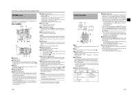
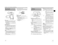
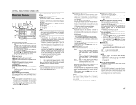
CONTROLS, INDICATORS AND CONNECTORS Left Side Section 98 7 1 2 3 CH2-AUDIO OUT-CH1 VIDEO IEEE 1394 0 6 5 4 1Viewfinder connector (6-pin) Connect the cable from the viewfinder here. 2[CH-2 INPUT] CH-2 audio input connector selector switch Selects the CH-2 audio input connector. INPUT1 INPUT2 : Inputs the audio from the INPUT1 connector 4 into CH-2. : Inputs the audio from the INPUT2 connector 4 into CH-2. MEMO The audio from the INPUT1 connector is also input into CH-1 regardless of the setting. 3[AUDIO INPUT] Audio input signal selector switch This switch is used to select the input sound signal from INPUT1 or INPUT2 connector. LINE : Set to this position when connected to audio equipment, etc. The reference input level is +4 dBs. MIC : Set to this position when the dynamic micro- phone is connected. MIC+48V : Set to this position when a microphone requiring +48 V power supply (phantom microphone, etc.) is connected. CAUTION When connecting a component that does not require +48 V power supply, make sure that the switch is not set to MIC+48V before the component is connected. MEMO You can select the normal input level for MIC and MIC+48V in the INPUT1, 2 MIC REF. item on the AUDIO/MIC[1/2] menu screen. X See page 84. 4[INPUT1/INPUT2] INPUT1/INPUT2 audio input connectors These are audio input connectors for connecting to an external audio device or microphone. • Set the [AUDIO INPUT] switch 3 according to the device to be connected. • Set the CH-2 audio input connector using the [CH-2 INPUT] switch 2. The CH-2 audio from the set connector is recorded. 5Shoulder pad slide button Button to adjust the position of the shoulder pad. When you press this button, you can move the position of the shoulder pad 6 forward or backward. 6Shoulder pad 7Cassette cover Sliding the EJECT switch a on page 18 located on the top section opens this cover to allow insertion or removal of the videocassette. CAUTION To prevent foreign objects from entering the internal parts of the VTR unit, do not leave this device with the cover open for extended periods of time. 8[VIDEO OUT] Video output terminal (RCA) This is a terminal for composite video signal output. • Select whether or not to output a signal with setup in SET UP on the VIDEO FORMAT[2/2] menu screen. (Only for U model) • Set ANALOG OUT CHAR. item on the OTHERS[1/2] menu screen to ON to output menu setting screens and warnings from this terminal. 9[AUDIO OUTPUT CH-1/CH-2] Audio output connector (RCA) Output connector for audio signals. • Outputs the input audio signal in the Camera mode. • Outputs the playback audio signal in the VTR mode. • When a HDV/DV signal (IEEE1394) is input, the EE sound of the input audio signal is output in the VTR mode. (HDV/DV signal input is possible with the GYHD200U/GY-HD201E.) MEMO Alarm sound is not output. 0[IEEE1394] IEEE1394 connector (6-pin) Using an IEEE1394 cable (optional), a digital video component with IEEE1394 connector can be connected here. X See "Connecting the IEEE1394 Cable" on page 63. X See "HDV/DV Dubbing" on page 65. CAUTION When connecting the IEEE1394 cable, confirm that the connector is facing the right direction before inserting. X See page 63. MEMO Put the covers on the connectors when you are not using them. 16 a b c d a[IEEE1394] IEEE1394 switch Set according to the image format of the input/output signal and playback signal of the IEEE1394 terminal. HDV : Set to this for HDV format. DV : Set to this for DV format. b[Y/PB/PR] Component Y/PB/PR signal output terminal (BNC × 3) Outputs analog component (Y/PB/PR) signals. • Select whether or not to add setup signals to DV format signals in SET UP item on the VIDEO FORMAT[2/2] menu screen. (Only for U model) • Set ANALOG OUT CHAR. item on the OTHERS[1/2] menu screen to ON to output menu setting screens and warnings from this terminal. c[REMOTE] REMOTE terminal (Round 6-pin) Some functions of this camera can be controlled externally. Connect to a remote control unit (RM-LP55/RM-LP57). X See "Connect a Remote Control Unit (RM-LP55/RMLP57)" on page 68. d[DC INPUT] DC input terminal (XLR 4-pin) This is the 12V DC power input terminal. Connect to the AC adapter. When a battery is installed and a cable is connected to this terminal, power supply from the battery stops and power is supplied by this terminal. IEEE 1394 CH2-AUDIO OUT-CH1 VIDEO 17
-
 1
1 -
2
-
3
-
4
-
5
-
 6
6 -
 7
7 -
 8
8 -
 9
9 -
 10
10 -
 11
11 -
 12
12 -
 13
13 -
 14
14 -
 15
15 -
 16
16 -
17
-
18
-
19
-
20
-
21
-
22
-
23
-
24
-
25
-
26
-
27
-
28
-
29
-
30
-
31
-
32
-
33
-
34
-
35
-
36
-
37
-
38
-
39
-
40
-
41
-
42
-
43
-
44
-
45
-
46
-
47
-
48
-
49
-
50
-
51
-
52
-
53
-
54
-
55
-
56
-
57
-
58
-
59
-
60
-
61
-
62
-
63
-
64
-
65
-
66
-
67
-
68
-
69
-
70
-
71
-
72
-
73
-
74
-
75
-
76
-
77
-
78
-
79
-
80
-
81
-
82
-
83
-
84
-
85
-
86
-
87
-
88
-
89
-
90
-
91
-
92
-
93
-
94
-
95
-
96
-
97
-
98
-
99
-
100
-
101
-
102
-
103
-
104
-
105
-
106
-
107
-
108
-
109
-
110
-
111
-
112
-
113
-
114
-
115
-
116
-
117
 |
 |
