JVC VN-C215VP4U Instruction Manual - Page 12
Name and Function of Parts, continued
 |
UPC - 046838030192
View all JVC VN-C215VP4U manuals
Add to My Manuals
Save this manual to your list of manuals |
Page 12 highlights
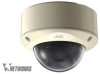
Introduction Name and Function of Parts (continued) Inside the camera L M N O P Q R S T U L [10BASE-T/100BASE-TX(PoE)] 10BASE-T/100BASE-TX terminal This is a 10BASE-T/100BASE-TX terminal. It connects to the network via LAN cable. (A Pg. 26) M Rotation Knob This knob rotates the lens section and adjusts the tilting of the image. (A Pg. 28) N Rotation center mark (A Pg. 28) O Fall-prevention wire It connects the base H to the dome cover E. P Camera Fastening Screw ן2 This secures the camera unit T and the base H. How to remove (A Pg. 17) Lens section (A Next page) b a Z Y X MAC address W V Q [RESET] Reset button This is a button for rebooting the camera. Press this button and release within 5 seconds to reboot the camera. It takes about 1 minute for the camera to reboot. During startup, [RESET] button is disabled. Noteɿ ● Pressing the [RESET] button for 5 seconds or longer switches the camera to the service verification mode. Do not press the button for 5 seconds or longer. R Status indicator This indicator appears blinking when the power is turned on and turns off when the camera startup is completed. Check the camera or the connected device if the indicator remains blinking when the camera is in use. 12
-
 1
1 -
2
-
3
-
4
-
5
-
6
-
 7
7 -
 8
8 -
 9
9 -
 10
10 -
 11
11 -
 12
12 -
 13
13 -
 14
14 -
 15
15 -
 16
16 -
 17
17 -
18
-
19
-
20
-
21
-
22
-
23
-
24
-
25
-
26
-
27
-
28
-
29
-
30
-
31
-
32
-
33
-
34
-
35
-
36
-
37
-
38
-
39
-
40
-
41
-
42
-
43
-
44
-
45
-
46
-
47
-
48
-
49
-
50
-
51
-
52
-
53
-
54
-
55
-
56
-
57
-
58
-
59
-
60
-
61
-
62
-
63
-
64
-
65
-
66
-
67
-
68
-
69
-
70
-
71
-
72
-
73
-
74
-
75
-
76
-
77
-
78
-
79
-
80
-
81
-
82
-
83
-
84
-
85
-
86
-
87
-
88
 |
 |
