Kenmore 8027 Use and Care Guide - Page 13
ii s02 - electric dryer manual
 |
UPC - 719192272088
View all Kenmore 8027 manuals
Add to My Manuals
Save this manual to your list of manuals |
Page 13 highlights
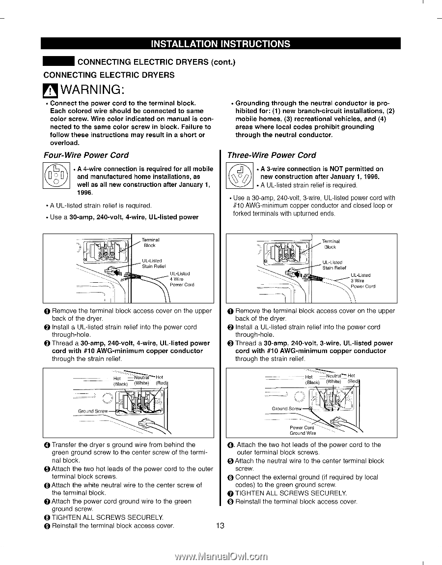
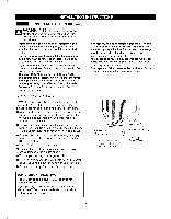
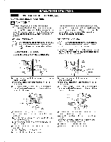
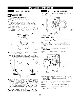
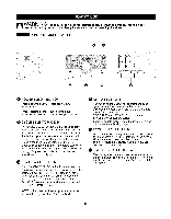
I I CONNECTING ELECTRIC DRYERS (cont.) CONNECTING ELECTRIC DRYERS WARNING" . Connect the power cord to the terminal block. Each colored wire should be connected to same color screw. Wire color indicated on manual is connected to the same color screw in block. Failure to follow these instructions may result in a short or overload. Four-Wire Power Cord © • A 4-wire connection is required for all mobile and manufactured home installations, as well as all new construction after January 1, 1996. • A UL-listed strain relief is required. ° Use a 30-amp, 240-volt, 4-wire, UL-listed power ° Grounding through the neutral conductor is prohibited for: (1) new branch-circuit installations, (2) mobile homes, (3) recreational vehicles, and (4) areas where local codes prohibit grounding through the neutral conductor. Three-Wire Power Cord © • A 3-wire connection is NOT permitted on new construction after January 1, 1996. • A UL-listed strain relief is required. • Use a 30-amp, 240-volt, 3-wire, UL-listed power cord with #10 AWG-minimum copper conductor and closed loop or forked terminals with upturned ends. Terminal Block UL-Listed Relief UL-Listed Power Cord Terminal Block UL-Listed Stain Relief UL-Listed 3 Wire Power Cord O Remove the terminal block access cover on the upper back of the dryer. O Install a UL-listed strain relief into the power cord through-hole. O Thread a 30-amp, 240-volt, 4-wire, UL-listed power cord with #10 AWG-minimum copper conductor through the strain relief. Hot ......N...e..u. tral"" Hot (Black) (White) (Red) O Remove the terminal block access cover on the upper back of the dryer. O Install a UL-listed strain relief into the power cord through-hole. O Thread a 30-amp, 240-volt, 3-wire, UL-listed power cord with #10 AWG-minimum copper conductor through the strain relief. Hot .......N...eutral"" Hot B. lack) (White)-- (Red)} ii s0..2.......... o ........ t Ground Wire -- "" O Transfer the dryer s ground wire from behind the green ground screw to the center screw of the termi- O. Attach the two hot leads of the power cord to the outer terminal block screws. nal block. O Attach the neutral wire to the center terminal block OAttach the two hot leads of the power cord to the outer terminal block screws. screw. O Connect the external ground (if required by local O Attach the white neutral wire to the center screw of codes) to the green ground screw. the terminal block. O TIGHTEN ALL SCREWS SECURELY. O Attach the power cord ground wire to the green O Reinstall the terminal block access cover. ground screw. O TIGHTEN ALL SCREWS SECURELY. O Reinstall the terminal block access cover. 13 I I
-
 1
1 -
2
-
3
-
4
-
5
-
6
-
7
-
 8
8 -
 9
9 -
 10
10 -
 11
11 -
 12
12 -
 13
13 -
 14
14 -
 15
15 -
 16
16 -
 17
17 -
 18
18 -
19
-
20
-
21
-
22
-
23
-
24
-
25
-
26
-
27
-
28
-
29
-
30
-
31
-
32
-
33
-
34
-
35
-
36
-
37
-
38
-
39
-
40
-
41
-
42
-
43
-
44
-
45
-
46
-
47
-
48
-
49
-
50
-
51
-
52
-
53
-
54
-
55
-
56
-
57
-
58
-
59
-
60
-
61
-
62
-
63
-
64
 |
 |