Kenmore 8027 Use and Care Guide - Page 8
Ikey Dimensions Iand Specifications - review
 |
UPC - 719192272088
View all Kenmore 8027 manuals
Add to My Manuals
Save this manual to your list of manuals |
Page 8 highlights
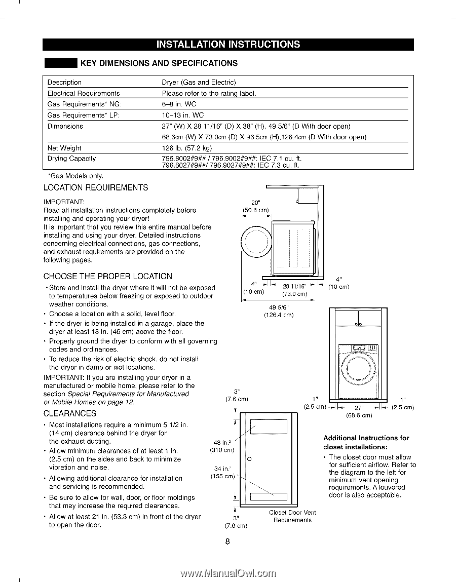
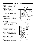
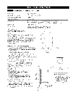
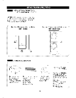
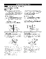
I I KEY DIMENSIONS AND SPECIFICATIONS Description Electrical Requirements Gas Requirements* NG: Gas Requirements* LP: Dimensions Net Weight Drying Capacity *Gas Models only. LOCATION REQUIREMENTS Dryer (Gas and Electric) Please refer to the rating label. 6-8 in. WC 10-13 in. WC 27" (W) X 28 11/16" (D) X 38" (H), 49 5/6" (D With door open) 68.6cm (W) X 73.0cm (D) X 96.5cm (H),126.4cm (D With door open) 126 lb. (57.2 kg) 796.8002#9## / 796.9002#9##: IEC 7.1 cu. ft. 796.8027#9##/796.9027#9##: IEC 7.3 cu. ft. ! IMPORTANT: Read all installation instructions completely before installing and operating your dryer! It is important that you review this entire manual before installing and using your dryer. Detailed instructions concerning electrical connections, gas connections, and exhaust requirements are provided on the following pages. 20" (50.8 cm) CHOOSE THE PROPER LOCATION • Store and install the dryer where it will not be exposed to temperatures below freezing or exposed to outdoor weather conditions. • Choose a location with a solid, level floor. • If the dryer is being installed in a garage, place the dryer at least 18 in. (46 cm) above the floor. I '' '' ' _11 4" _11-_,_2811/16''-_ I-_ (10 cm) (73.0 cm) _ (10 cm) 49 5/6" (126.4 cm) oo • Properly ground the dryer to conform with all governing codes and ordinances. • To reduce the risk of electric shock, do not install the dryer in damp or wet locations. IMPORTANT: If you are installing your dryer in a manufactured or mobile home, please refer to the section Special Requirements for Manufactured or Mobile Homes on page 12. CLEARANCES • Most installations require a minimum 5 1/2 in. (14 cm) clearance behind the dryer for the exhaust ducting. • Allow minimum clearances of at least 1 in. (2.5 cm) on the sides and back to minimize vibration and noise. • Allowing additional clearance for installation and servicing is recommended. • Be sure to allow for wall, door, or floor moldings that may increase the required clearances. • Allow at least 21 in. (53.3 cm) in front of the dryer to open the door. 3 II (7.6 cm) i 48 in.2 J (310 cm) iO 34 in. 2 (155 cm) \ 3" (7.6 cm) 1 ii 1 ii (2.5 cm) -_11_ 27" _ _- (2.5 cm) (68.6 cm) I Additional Instructions for closet installations: • The closet door must allow for sufficient airflow. Refer to the diagram to the left for minimum vent opening requirements. A Iouvered door is also acceptable. Closet Door Vent Requirements 8 I I
-
 1
1 -
2
-
 3
3 -
 4
4 -
 5
5 -
 6
6 -
 7
7 -
 8
8 -
 9
9 -
 10
10 -
 11
11 -
 12
12 -
 13
13 -
14
-
15
-
16
-
17
-
18
-
19
-
20
-
21
-
22
-
23
-
24
-
25
-
26
-
27
-
28
-
29
-
30
-
31
-
32
-
33
-
34
-
35
-
36
-
37
-
38
-
39
-
40
-
41
-
42
-
43
-
44
-
45
-
46
-
47
-
48
-
49
-
50
-
51
-
52
-
53
-
54
-
55
-
56
-
57
-
58
-
59
-
60
-
61
-
62
-
63
-
64
 |
 |