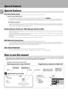
Kenwood C-V351 User Manual - Page 5
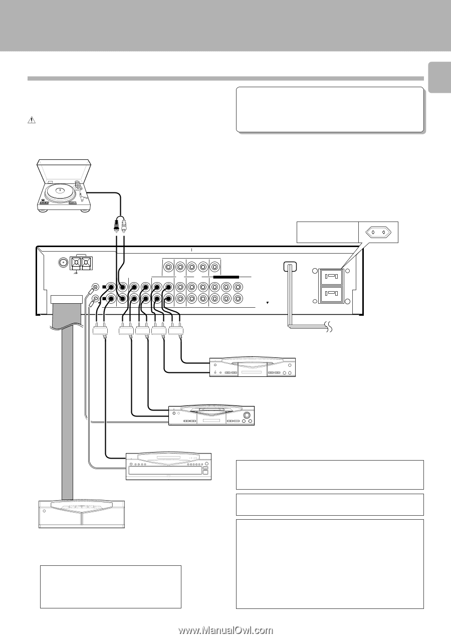
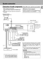
System connection, Connection of audio components (CD player, MD recorder, cassette deck
 |
View all Kenwood C-V351 manuals
Add to My Manuals
Save this manual to your list of manuals |
Page 5 highlights
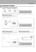
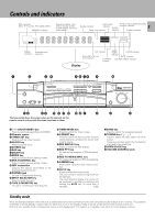
System connection C-V351/C-V301 (EN) Connection of audio components (CD player, MD recorder, cassette deck, power amplifier) 5 Make connection as shown below. When connecting the related system components, refer also to the instruction manuals of the related components. Do not plug in the power lead until all connections are completed. Malfunction of microcomputer If operation is not possible or erroneous display appears even though all connections have been made properly, reset the microcomputer referring to "In case of difficulty". R Analog disc turntable (with built-in equalizer amp) ANTENNA AM VIDEO DVD FM 75Ω GND CONNECT WITH POWER AMPLIFIER SYSTEM CD CONTROL L R IN AUX TAPE 1/ MD MONITOR OUT TAPE 2 (MONITOR) LD /DVD VCR DVD 6CH.INPUT CENTER IN REC PLAY REC PLAY IN REC PLAY FRONT SURROUND SUBWOOFER AUDIO PLAY OUT *2 Graphic equalizer or Cassette deck 2 REC IN REC IN PLAY OUT MD recorder or Cassette deck 1 Shape of AC outlet Europe UNSWITCHED CAUTION (For U.K.) When using the AC outlets equipped with this unit, be sure to consult your dealer for the corresponding plug. To wall AC outlet Connection cable System control cord LINE OUTPUT System control cord CD player *1 Power amplifier *1 For the connection and operation procedures of the power amplifier and speakers, refer to the instruction manual of the power amplifier (M-A300 or M-A100). The connected components shown here are given as examples because the available models vary depending on marketing areas. Also connect the system control cords when the KENWOOD Audio Component System "SERIES 21" is connected. *2 Do not connect system control cord to the cassette deck connected to the TAPE 2 (MONITOR) jacks. CAUTION Be sure to adhere followings. Or proper ventilation will be blocked causing damage or fire hazard. ÷ Install the R-SE7 on the top of the system. ÷ Do not place any objects impairing heat radiation onto the top of unit. ÷ Leave a space around the unit (from the largest outside di- mension including projection) equal or greater than, shown below. Top panel : 50 cm Side panel : 10 cm Back panel : 10 cm
-
 1
1 -
 2
2 -
 3
3 -
 4
4 -
 5
5 -
 6
6 -
 7
7 -
 8
8 -
 9
9 -
 10
10 -
 11
11 -
12
-
13
-
14
-
15
-
16
-
17
-
18
-
19
-
20
-
21
-
22
-
23
-
24
-
25
-
26
-
27
-
28
-
29
-
30
-
31
-
32
-
33
-
34
-
35
-
36
-
37
-
38
-
39
-
40
-
41
-
42
-
43
-
44
-
45
-
46
-
47
-
48
-
49
-
50
-
51
-
52
-
53
-
54
-
55
-
56
 |
 |