LG 50PX2DC Owners Manual - Page 14
Analog and Digital, signals provided on cable, Option - owners manual
 |
UPC - 719192169579
View all LG 50PX2DC manuals
Add to My Manuals
Save this manual to your list of manuals |
Page 14 highlights
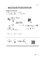
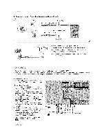
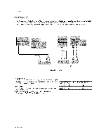
Installation 3, Analog and Digital TV signals provided on cable and antenna /f Antenna Bronze Wire Cable TV Wall Jack Turn clockwise to tighten. RF Coaxia_ Wire (75 ohm) Bronze Wire ij • To improve the pict_Jre quality in a poor signa_ area, please purchase a sign_ _plifier and install properly. • If the antenna needs to be split for two TV's, install a '_Way Signa_ Splitte¢' in the connections. • If the antenna is not installed proper_y, cart#act your dealer for assistance. - To avoid picture noise (interference), leave an adequate distance between the VCR and "P.7 - Use the ISM Method (on the Option menu) feature to avoid having a fix_ image remain on the screen for a _eng period ef time If the 4:3 picture format is used; the fixed images on the sides of the screen may remain visible en the screen Connection Option 1 Set VCR eutput swish to channel 3 or 4 and then tune the TV to the same channel number Connection Option 2 1, Connect the audio and video cables from the VCRs output jacks to the TV input jacks_ as shown in the figure, When connecting the TV to VCR, match the jack colors (Vi_o = yellow, Audio Left = white, and Audio Right = red), If you connect an S-WDEO output from VCR to the S-V_DEO input, the picture quality is improved; compared to connecting a regular VCR to the Video input 2, Unsert a video tape into the VCR and press PLAY on the VCR_ (Refer to the VCR owner's manual ) &Seiect the inp_ source with using the _/VIDEO bu_on on the remote control, Note that this TV finds the connected input sources automatically for Video, Front Video and Component 1-2. It is presumed that RGB and HDMI/DW sources are connected, De not connect to both Vi_o and S_Video at the same time, [] VCR Rear 14 P_a TV
-
 1
1 -
2
-
3
-
4
-
5
-
6
-
7
-
8
-
 9
9 -
 10
10 -
 11
11 -
 12
12 -
 13
13 -
 14
14 -
 15
15 -
 16
16 -
 17
17 -
 18
18 -
 19
19 -
20
-
21
-
22
-
23
-
24
-
25
-
26
-
27
-
28
-
29
-
30
-
31
-
32
-
33
-
34
-
35
-
36
-
37
-
38
-
39
-
40
-
41
-
42
-
43
-
44
-
45
-
46
-
47
-
48
-
49
-
50
-
51
-
52
-
53
-
54
-
55
-
56
-
57
-
58
-
59
-
60
 |
 |
