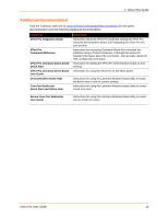
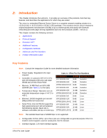
Lantronix XPort Pro XPort Pro - User Guide - Page 19
Configuration Methods, Addresses and Port Numbers, Hardware Address, IP Address, Port Numbers - xport programming
 |
View all Lantronix XPort Pro manuals
Add to My Manuals
Save this manual to your list of manuals |
Page 19 highlights
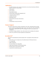
2: Introduction Configuration Methods After installation, the XPort Pro requires configuration. For the unit to operate correctly on a network, it must have a unique IP address on the network. There are four basic methods for logging into the XPort Pro and assigning IP addresses and other configurable settings: DeviceInstaller: Configure the IP address and related settings and view current settings on the XPort Pro using a Graphical User Interface (GUI) on a PC attached to a network. See Using DeviceInstaller (on page 21). Web Manager: Through a web browser, configure the XPort Pro settings using the Lantronix Web Manager. See Configuration Using Web Manager (on page 23). Command Mode: There are two methods for accessing Command Mode (CLI): making a Telnet connection or connecting a terminal (or a PC running a terminal emulation program) to the unit's serial port. (See the XPort Pro Command Reference Guide for instructions and available commands.) XML: The XPort Pro supports XML-based configuration and setup records that make device configuration transparent to users and administrators. XML is easily editable with a standard text or XML editor. (See the XPort Pro Command Reference Guide for instructions and commands.) Addresses and Port Numbers Hardware Address The hardware address is also referred to as the Ethernet address or MAC address. The first three bytes of the Ethernet address are fixed and read 00-20-4A, identifying the unit as a Lantronix product. The fourth, fifth, and sixth bytes are unique numbers assigned to each unit. Figure 2-2 Sample Hardware Address 00-20-4A-14-01-18 or 00:20:4A:14:01:18 IP Address Every device connected to an IP network must have a unique IP address. This address references the specific unit. Port Numbers Every TCP connection and every UDP datagram is defined by a destination and source IP address, and a destination and source port number. For example, a Telnet server commonly uses port number 23. The following is a list of the default server port numbers running on the XPort Pro: TCP Port 22: SSH Server (Command Mode configuration) TCP Port 23: Telnet Server (Command Mode configuration) TCP Port 80: HTTP (Web Manager configuration) TCP Port 443: HTTPS (Web Manager configuration) UDP Port 161: SNMP TCP Port 21: FTP XPort Pro User Guide 19
-
 1
1 -
2
-
3
-
4
-
5
-
6
-
7
-
8
-
9
-
10
-
11
-
12
-
13
-
 14
14 -
 15
15 -
 16
16 -
 17
17 -
 18
18 -
 19
19 -
 20
20 -
 21
21 -
 22
22 -
 23
23 -
 24
24 -
25
-
26
-
27
-
28
-
29
-
30
-
31
-
32
-
33
-
34
-
35
-
36
-
37
-
38
-
39
-
40
-
41
-
42
-
43
-
44
-
45
-
46
-
47
-
48
-
49
-
50
-
51
-
52
-
53
-
54
-
55
-
56
-
57
-
58
-
59
-
60
-
61
-
62
-
63
-
64
-
65
-
66
-
67
-
68
-
69
-
70
-
71
-
72
-
73
-
74
-
75
-
76
-
77
-
78
-
79
-
80
-
81
-
82
-
83
-
84
-
85
-
86
-
87
-
88
-
89
-
90
-
91
-
92
-
93
-
94
-
95
-
96
-
97
-
98
-
99
-
100
-
101
-
102
-
103
-
104
-
105
-
106
-
107
-
108
-
109
-
110
-
111
-
112
-
113
-
114
-
115
-
116
-
117
-
118
-
119
-
120
-
121
-
122
-
123
-
124
-
125
-
126
-
127
-
128
-
129
-
130
-
131
-
132
-
133
-
134
-
135
-
136
-
137
-
138
-
139
-
140
-
141
-
142
-
143
-
144
-
145
-
146
-
147
-
148
-
149
-
150
-
151
-
152
-
153
-
154
 |
 |
