Lenovo B520 Lenovo IdeaCentre B520 Hardware Maintenance Manual
Lenovo B520 Manual
 |
View all Lenovo B520 manuals
Add to My Manuals
Save this manual to your list of manuals |
Lenovo B520 manual content summary:
- Lenovo B520 | Lenovo IdeaCentre B520 Hardware Maintenance Manual - Page 1
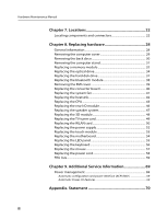
Viewing and changing settings 15 Using passwords 16 Selecting a startup device 18 Exiting from the Setup Utility program 19 Chapter 6. Symptom-to-FRU Index 20 Hard disk drive boot error 20 Power Supply Problems 20 Beep symptoms 21 POST error codes 21 i - Lenovo B520 | Lenovo IdeaCentre B520 Hardware Maintenance Manual - Page 2
system 47 Replacing the 3D module 48 Replacing the TV tuner card 49 Replacing the WLAN card 50 Replacing the power supply 52 Replacing the touch module 53 Replacing the motherboard 54 Replacing the LED panel 55 Replacing the keyboard 56 Replacing the mouse 57 Replacing the power cord 58 - Lenovo B520 | Lenovo IdeaCentre B520 Hardware Maintenance Manual - Page 3
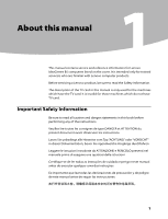
B5 computers listed on the cover. It is intended only for trained servicers who are familiar with Lenovo computer products. Before servicing a Lenovo product, be sure to read the Safety Information. The description of the TV card in this manual is only used for the machines which have the TV - Lenovo B520 | Lenovo IdeaCentre B520 Hardware Maintenance Manual - Page 4
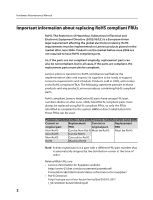
Hardware Maintenance Manual Important information about replacing RoHS compliant FRUs RoHS, The Restriction the replacement parts must also be compliant. Lenovo plans to transition to RoHS compliance well before the implementation date and expects its suppliers to be ready to support Lenovo's - Lenovo B520 | Lenovo IdeaCentre B520 Hardware Maintenance Manual - Page 5
Chapter 1. About this manual •• California Senate Bills 20, 50: http://www.ciwmb.ca.gov/HHW/Events/AnnualConf/2004/ presentation/MPaparian.pdf 3 - Lenovo B520 | Lenovo IdeaCentre B520 Hardware Maintenance Manual - Page 6
Hardware Maintenance Manual Safety information 2 This chapter contains the safety information that you need to be familiar with before servicing a computer. General safety Follow these rules to ensure general safety: •• Observe good housekeeping in the area of the machines during and after - Lenovo B520 | Lenovo IdeaCentre B520 Hardware Maintenance Manual - Page 7
•• Wear safety glasses when you are: hammering, drilling soldering, cutting wire, attaching springs, using solvents, or working in any other conditions that might be hazardous to your eyes. •• After service, reinstall all safety shields, guards, labels, and ground wires. Replace any safety device - Lenovo B520 | Lenovo IdeaCentre B520 Hardware Maintenance Manual - Page 8
safety precautions when you work with very high voltages; these instructions are in the safety sections touching can cause personal injury and machine damage. •• Do not service the following parts with the power on when they are removed from their normal operating places in a machine: - Power supply - Lenovo B520 | Lenovo IdeaCentre B520 Hardware Maintenance Manual - Page 9
installed to protect users and service personnel from injury. This guide addresses only those items. However problem. Consider these conditions and the safety hazards they present: •• Electrical hazards, especially primary power that the power-supply cover fasteners (screws or rivets) have not been removed - Lenovo B520 | Lenovo IdeaCentre B520 Hardware Maintenance Manual - Page 10
Manual . •• Prevent the part from touching your clothing. Most clothing is work mat to provide a static-free work surface. The mat is especially useful when handling ESD-sensitive devices. •• Select a grounding system, such as those listed below, to provide protection that meets the specific service - Lenovo B520 | Lenovo IdeaCentre B520 Hardware Maintenance Manual - Page 11
equipment that will be attached to this product. •• When possible, use one hand only to connect or disconnect signal cables. •• Never turn on any Disconnect the attached power cords, telecommunications systems, networks, and modems before you open the device covers, unless instructed otherwise in - Lenovo B520 | Lenovo IdeaCentre B520 Hardware Maintenance Manual - Page 12
or immerse into water •• Heat to more than 100°C (212°F) •• Repair or disassemble Dispose of the battery as required by local ordinances or regulations. CAUTION: When laser products (such as CD-ROMs, DVD-ROM drives, fiber optic devices, or transmitters) are installed, note the following: •• Do not - Lenovo B520 | Lenovo IdeaCentre B520 Hardware Maintenance Manual - Page 13
CAUTION: Use safe practices when lifting. CAUTION: The power control button on the device and the power switch on the power supply do not turn off the electrical current supplied to the device. The device also might have more than one power cord. To remove all electrical current from the device - Lenovo B520 | Lenovo IdeaCentre B520 Hardware Maintenance Manual - Page 14
that applies to all machine types supported by this publication. Specifications This section lists the physical specifications for your computer. Type Lenovo IdeaCentre B5 This section lists the physical specifications. Environment Air temperature: Operating: 10° to 35°C Transit: -20° to 55 - Lenovo B520 | Lenovo IdeaCentre B520 Hardware Maintenance Manual - Page 15
Checkout Attentions The drives in the computer you are servicing might have been rearranged or the drive startup sequence changed. false errors and unnecessary replacement of the system board. Use the following procedure to help determine the cause of the problem: 1. Power-off the computer and - Lenovo B520 | Lenovo IdeaCentre B520 Hardware Maintenance Manual - Page 16
following information to assist you in problem determination. If possible, have this information available when requesting assistance from Service Support and Engineering functions. •• Machine type and model •• Processor or hard disk upgrades •• Failure symptom - Do diagnostics indicate a failure - Lenovo B520 | Lenovo IdeaCentre B520 Hardware Maintenance Manual - Page 17
computer. Notes: a. If you are using a USB keyboard and the Setup Utility program does not display using this when turning on the computer. b. If a Power-On Password or an administrator password has been set ." When working with the Setup Utility program menu, you must use the keyboard. The keys - Lenovo B520 | Lenovo IdeaCentre B520 Hardware Maintenance Manual - Page 18
should adhere to the following rules: • Must have at least seven characters in length • Contain at least one alphabetic character and one numeric character • Setup Utility program and hard disk drive passwords are not case sensitive • Not be your name or your user name • Not be a common word - Lenovo B520 | Lenovo IdeaCentre B520 Hardware Maintenance Manual - Page 19
is set, you cannot start the Setup Utility program until a valid password is typed from the keyboard. Setting, changing, and deleting a Power-On Password To set, change, or delete a Power-On Password, do the following: Note A password can be any combination of up to 64 characters (a-z , 0-9). 17 - Lenovo B520 | Lenovo IdeaCentre B520 Hardware Maintenance Manual - Page 20
Hardware Maintenance Manual 1. Start the Setup Utility program (See Starting the Setup Utility program .) 2. From the Security menu, select Set Power-On from a device such as the CD-ROM, diskette, or hard disk as expected, use one of the following procedures to select a startup device. Selecting a - Lenovo B520 | Lenovo IdeaCentre B520 Hardware Maintenance Manual - Page 21
Chapter 5. Using the Setup Utility Selecting or changing the startup device sequence To view or permanently change the configured startup device sequence, do the following: 1. Start the Setup Utility program (see Starting the Setup Utility program on page 15). 2. Select Start Up. 3. Select Primary - Lenovo B520 | Lenovo IdeaCentre B520 Hardware Maintenance Manual - Page 22
. Hard disk drive boot error A hard disk drive boot error (error codes 1962) can have the following causes. Error No operating system found. Press any key to repeat boot sequence. FRU/Action Install an operating system on the boot drive. Power Supply Problems If you suspect a power problem - Lenovo B520 | Lenovo IdeaCentre B520 Hardware Maintenance Manual - Page 23
Power-On Self-Test, or POST. POST does the following operations. • Checks some basic system-board operations • Checks the memory operation • Starts the video operation • Verifies that the boot drive is working If the POST detects a problem, an error message appears on the screen. A single problem - Lenovo B520 | Lenovo IdeaCentre B520 Hardware Maintenance Manual - Page 24
Hardware Maintenance Manual Locations 7 This section provides illustrations to help locate the various connectors, controls and components of the computer. Font view The following illustration shows the location of connectors on the front of the computer. 1 2 3 45 6 7 8 9 10 11 12 13 14 15 22 - Lenovo B520 | Lenovo IdeaCentre B520 Hardware Maintenance Manual - Page 25
2 Camera 3 Power button 4 Hard Disk Drive Indicator 5 Bluetooth status indicator 6 WIFI status indicator 7 AV-in / HDMI-in indicator Monitor On/Off 8 Indicator lights ON/OFF button 9 Volume down 10 Volume up 11 Brightness vents on the computer. Blocked air vents may cause thermal problems. 23 - Lenovo B520 | Lenovo IdeaCentre B520 Hardware Maintenance Manual - Page 26
Hardware Maintenance Manual 1 Memory card reader 2 USB connector 3 Headphone connector 4 Microphone connector 5 Optical drive Rear view The following illustration shows the location of connectors on the rear of the computer. 24 - Lenovo B520 | Lenovo IdeaCentre B520 Hardware Maintenance Manual - Page 27
Chapter 7. Locations 1 Power socket 2 Ethernet port 3 USB ports (4) 4 HDMI in port (Selected models only) 5 HDMI out port 6 PS/2 keyboard port 7 Bluetooth reset button (Only functional on models equipped with bluetooth module) 8 AV-IN ports (Selected models only) 9 TV tuner connector (Selected - Lenovo B520 | Lenovo IdeaCentre B520 Hardware Maintenance Manual - Page 28
Manual 8 TV turner card 9 WLAN card 10 3D IR emitter 11 Bluetooth module 12 Rear I/O module 13 Camera 14 Touch module 15 Converter 16 System fans 17 Heatsink 18 3D module 19 Motherboard 20 Power supply 21 Chassis 22 LED panel 23 Front bezel Identifying parts on the motherboard The motherboard - Lenovo B520 | Lenovo IdeaCentre B520 Hardware Maintenance Manual - Page 29
connector 7 Fan connector-2 8 Mini PCI connector 9 Mini PCI connector 10 Front touch sensor board connector 11 Hard and optical disk drive power connectors 12 3D module connector 13 SATA connectors 14 Mini PCI connector 15 Power supply connector 16 BIOS battery 17 Rear I/O connector 18 5.0 speaker - Lenovo B520 | Lenovo IdeaCentre B520 Hardware Maintenance Manual - Page 30
in the Hardware Maintenance Manual (HMM) for the computer. To obtain copies of the Safety and Warranty Guide or HMM, go to the Support Web site at: http://consumersupport.lenovo.com. Note Use only parts provided by Lenovo. General information Pre-disassembly instructions Before proceeding with the - Lenovo B520 | Lenovo IdeaCentre B520 Hardware Maintenance Manual - Page 31
flat surface for this procedure. Lenovo recommends that you use a blanket, towel, or other soft cloth to protect the computer screen from scratches or other damage. To remove the computer cover 1. Remove any media (disks, CDs, or memory cards) from the drives, shut down the operating system, and - Lenovo B520 | Lenovo IdeaCentre B520 Hardware Maintenance Manual - Page 32
a soft flat surface for this procedure. Lenovo recommends that you use a blanket, towel, or other soft cloth to protect the computer screen from scratches or other damage. To remove the back deco: 1. Remove any media (disks, CDs, or memory cards) from the drives, shut down the operating system, and - Lenovo B520 | Lenovo IdeaCentre B520 Hardware Maintenance Manual - Page 33
place the computer face-down on a soft flat surface. Lenovo recommends that you use a blanket, towel, or other soft cloth to protect the screen surface from scratches or other damage. 1. Remove any media (disks, CDs, or memory cards) from the drives, shut down the operating system, and turn off the - Lenovo B520 | Lenovo IdeaCentre B520 Hardware Maintenance Manual - Page 34
the stand up and out. Replacing a memory module Attention Turn off the computer and wait 3 to 5 minutes to let the computer cool down before removing the computer cover. Note It may be helpful to place the computer face-down on a soft flat surface for this procedure. Lenovo recommends that you use - Lenovo B520 | Lenovo IdeaCentre B520 Hardware Maintenance Manual - Page 35
8. Replacing hardware 1. Remove any media (disks, CDs, or memory cards) from the drives, shut down the operating system, and turn off the computer and all attached devices. 2. Unplug all power cords from electrical outlets. 3. Disconnect all cables attached to the computer. This includes power cords - Lenovo B520 | Lenovo IdeaCentre B520 Hardware Maintenance Manual - Page 36
computer face-down on a soft flat surface for this procedure. Lenovo recommends that you use a blanket, towel, or other soft cloth to protect the screen from scratches or other damage. 1. Remove any media (disks, CDs, or memory cards) from the drives, shut down the operating system, and turn off the - Lenovo B520 | Lenovo IdeaCentre B520 Hardware Maintenance Manual - Page 37
Chapter 8. Replacing hardware 6. Push the optical drive so that it slides out of the drive bay. 7. Push a small iron stick (e.g.a paper clip) into the small hole on the optical drive cover so that the optical drive springs out as shown. 8. Remove the 2 screws that secure the optical drive to the - Lenovo B520 | Lenovo IdeaCentre B520 Hardware Maintenance Manual - Page 38
Hardware Maintenance Manual 10. Separate the cover from the defective optical drive. 11. Install the new optical drive as follows: (1) Align the new optical drive with the cover, then push the cover back into position. (2) Secure the metal bracket onto the new optical drive using the 2 screws. - Lenovo B520 | Lenovo IdeaCentre B520 Hardware Maintenance Manual - Page 39
cool down before replacing the hard disk drive. To replace the hard disk drive: Note It may be helpful to place the computer face-down on a soft flat surface for this procedure. Lenovo recommends that you use a blanket, towel, or other soft cloth to protect the screen from scratches or other - Lenovo B520 | Lenovo IdeaCentre B520 Hardware Maintenance Manual - Page 40
the new hard disk drive to the drive bay using the 4 screws. 6. Slide the hard disk drive bay back into position. 7. Secure the hard disk drive bay to the chassis with the remaining screw. 8. Slide the computer cover back into position. Replacing the bluetooth module To replace the bluetooth module - Lenovo B520 | Lenovo IdeaCentre B520 Hardware Maintenance Manual - Page 41
Chapter 8. Replacing hardware 4. Disconnect the antenna cable from the bluetooth module. 5. Connect the antenna cable to the new bluetooth module. 6. Line up the bluetooth module then push it into position. 7. Slide the back deco into position. Removing the EMI cover 1. Remove the computer cover. - Lenovo B520 | Lenovo IdeaCentre B520 Hardware Maintenance Manual - Page 42
Hardware Maintenance Manual 4. Remove the 19 screws that secure the EMI cover to the chassis and lift up the EMI cover. Replacing the converter board To replace the converter board: 1. Remove the computer cover. Refer to "Removing the computer cover". 2. Remove the back deco. Refer to "Removing the - Lenovo B520 | Lenovo IdeaCentre B520 Hardware Maintenance Manual - Page 43
cover, back deco, the computer cover and computer stand. Replacing the system fan To replace the system fan: 1. Remove the computer cover. Refer to cover. Refer to "Removing the EMI cover". 5. Disconnect the power cables from the motherboard and remove the cables attached to the system fan. 6. Remove - Lenovo B520 | Lenovo IdeaCentre B520 Hardware Maintenance Manual - Page 44
Hardware Maintenance Manual 7. Remove the system fan by lifting it up. 8. Line up the new system fan then secure it to the chassis and motherboard with the screws. 9. Reattach the EMI cover, back deco, the computer cover and computer stand. Replacing the heatsink To replace the heatsink: 1. Remove - Lenovo B520 | Lenovo IdeaCentre B520 Hardware Maintenance Manual - Page 45
it up. 8. Line up the new heatsink then secure it to the motherboard with the screws. 9. Attach the system fan to the new heatsink. 10. Reattach the EMI cover, back deco, the computer cover and computer stand. Replacing the CPU To replace the CPU: 1. Remove the computer cover. Refer to "Removing the - Lenovo B520 | Lenovo IdeaCentre B520 Hardware Maintenance Manual - Page 46
Hardware Maintenance Manual 8. Lift the microprocessor straight up and out of the socket. Note a. Note the orientation of the notches 1 on the microprocessor. This is important when installing the new microprocessor on the motherboard. b. Do not drop anything onto the microprocessor socket while it - Lenovo B520 | Lenovo IdeaCentre B520 Hardware Maintenance Manual - Page 47
Chapter 8. Replacing hardware 9. Make sure that the microprocessor retainer is fully open. 10. Holding the sides of the microprocessor with your fingers, remove the protective cover 2 that protects the into the socket. 12. Lower the microprocessor straight down into its socket on the motherboard. 45 - Lenovo B520 | Lenovo IdeaCentre B520 Hardware Maintenance Manual - Page 48
Hardware Maintenance Manual 13. To secure the EMI cover, back deco, the computer cover and the computer stand back. Replacing the rear I/O module To replace the rear I/O module: 1. Remove the computer cover. Refer to "Removing antenna cable from the TV tuner card. 7. Lift up the rear I/O module. 46 - Lenovo B520 | Lenovo IdeaCentre B520 Hardware Maintenance Manual - Page 49
2 10. Line the new I/O module up then slide it into the metal bracket. 11. Line the new I/O module up with the chassis then secure it with the screws. 12. Connect the new TV antenna cable to the motherboard. 13. Reattach the EMI cover, back deco, the computer cover and computer stand. Replacing the - Lenovo B520 | Lenovo IdeaCentre B520 Hardware Maintenance Manual - Page 50
Manual 7. Lift up the speaker system. 8. Line up the new speaker system with the chassis then secure it using the screws. 9. Connect the new speaker cables to the motherboard. 10. Reattach the EMI cover, back deco, the computer cover and computer stand. Replacing the 3D module To replace the 3D - Lenovo B520 | Lenovo IdeaCentre B520 Hardware Maintenance Manual - Page 51
the new 3D module up with the motherboard then secure it with the screws. 10. Connect all the cables to the new 3D module. 11. Reattach the rear I/O module. 12. Reattach the EMI cover, back deco, computer cover and computer stand. Replacing the TV tuner card To replace the TV tuner card: 1. Remove - Lenovo B520 | Lenovo IdeaCentre B520 Hardware Maintenance Manual - Page 52
motherboard. 7. Pull the TV tuner card upward to remove it from the card port. 8. Line up the new TV tuner card then secure it with the screw. 9. Connect the antenna cable to the new TV tuner card. 10. Reattach the EMI cover, back deco, the computer cover and computer stand. Replacing the WLAN card - Lenovo B520 | Lenovo IdeaCentre B520 Hardware Maintenance Manual - Page 53
Chapter 8. Replacing hardware 8. Pull the WLAN card upward to remove it from the card port. 9. Separate the WLAN card from the metal bracket by removing the 2 screws. 10. Secure the new WLAN card to the metal bracket with the 2 screws. 11. Line the new WLAN card up with the card port and secure it - Lenovo B520 | Lenovo IdeaCentre B520 Hardware Maintenance Manual - Page 54
Hardware Maintenance Manual 13. Reattach the TV tuner card. 14. Reattach the EMI cover, back deco, the computer cover and computer stand. Replacing the power supply To replace the power supply: 1. Remove the computer cover. Refer to "Removing the computer cover". 2. Remove the back deco. Refer to " - Lenovo B520 | Lenovo IdeaCentre B520 Hardware Maintenance Manual - Page 55
system fan. Refer to "Replacing the system fan ". 6. Remove the 2 screws that secure the touch module to the chassis. 7. Lift up the touch module. 8. Disconnect the 3 cables from the touch module. 9. Connect the 3 cables to the new touch module. 10. Line up the new touch module and secure it using - Lenovo B520 | Lenovo IdeaCentre B520 Hardware Maintenance Manual - Page 56
9. Remove the 3D module. Refer to "Replacing the 3D module" 10. Remove the CPU. Refer to "Replacing the CPU". 11. Remove the TV tuner card. Refer to "Replacing the TV tuner card". 12. Remove the WLAN card. Refer to "Replacing the WLAN card". 13. Remove all the cables connected to the motherboard. 14 - Lenovo B520 | Lenovo IdeaCentre B520 Hardware Maintenance Manual - Page 57
to the chassis using the 4 screws. 18. Attach all related components to the new motherboard. 19. Reattach the EMI cover, back deco, the computer cover and computer stand. Replacing the LED panel To replace the LED panel: 1. Remove the computer cover. Refer to "Removing the computer cover". 2. Remove - Lenovo B520 | Lenovo IdeaCentre B520 Hardware Maintenance Manual - Page 58
in the Hardware Maintenance Manual (HMM) for the computer. To obtain copies of the Safety and Warranty Guide or HMM, go to the Support Web site at: http://consumersupport.lenovo.com. To replace the keyboard: 1. Remove any media (disks, CDs, or memory cards) from the drives, shut down the operating - Lenovo B520 | Lenovo IdeaCentre B520 Hardware Maintenance Manual - Page 59
or in the Hardware Maintenance Manual (HMM) for the computer. To obtain copies of the Safety and Warranty Guide or HMM, go to the Support Web site at: http://consumersupport.lenovo.com. To replace the mouse: 1. Remove any media (disks, CDs, or memory cards) from the drives, shut down the operating - Lenovo B520 | Lenovo IdeaCentre B520 Hardware Maintenance Manual - Page 60
Hardware Maintenance Manual (HMM) for the computer. To obtain copies of the Safety and Warranty Guide or HMM, go to the Support Web site at: http://consumersupport.lenovo.com. To replace the power cord and power adapter: 1. Remove any media (disks, CDs, or memory cards) from the drives, shut down - Lenovo B520 | Lenovo IdeaCentre B520 Hardware Maintenance Manual - Page 61
view for help with locating the connector". FRU lists 3. Disconnect the defective power cord from the computer and connect the new power cord to the same connector. This chapter lists the information on the field replaceable units (FRUs). Attention Be sure to read and understand all the safety - Lenovo B520 | Lenovo IdeaCentre B520 Hardware Maintenance Manual - Page 62
Manual Item # 19 Description Motherboard B520 H67 N12P_GT1_1G MB B520 H67 N12P_GT1_2G MB B520 H67 N12P_GT1_1G_3D MB B520 H67 N12P_GT1_2G_3D MB B520 H67 W/O GPU MB B520 H67 W/O GPU W/0 AV MB B520 H67 N12P_GT1_1G W/0 AV MB B520 H67 N12P_GT1_2G W/0 AV MB B520 H67 N12P_GT1_1G_3D W/0 AV MB B520 Service - Lenovo B520 | Lenovo IdeaCentre B520 Hardware Maintenance Manual - Page 63
H5GQ1H24AFR-T2L K4G20325FC-HC04 H5GQ2H24MFR-T2C Memory M471B2873FHS-CH9 1GB DDRIII1333 S_ 4GB DDRIII1333 S_ Hard Drive WD3200AAJS-08L7A0 Samsung MZMPA032HMCD 32G mSATA Optical Drive GT30N 6 TS-L633F DS-8A5SH PLDS DS-6E2SH Slim BD Combo w/o bezel Chapter 8. Replacing hardware 1-007154 - Lenovo B520 | Lenovo IdeaCentre B520 Hardware Maintenance Manual - Page 64
Hardware Maintenance Manual 6 20 9 8 16 22 11 13 62 HLDS CT30N Slim BD Combo w/o bezel TS-LB23D BD-5740H Power Supply Acbel APA006-EL0G ES5.0 200w PSU_ Huntkey HKF2002-32 ES5.0 200W PSU_ Liteon PS-3251-01VA ES 5.0 250w PSU_ Delta DPS-250AB-71A ES5.0 250W PSU_ Wireless Card Liteon AR9285 HB95 BGN - Lenovo B520 | Lenovo IdeaCentre B520 Hardware Maintenance Manual - Page 65
1.8m Power Cord_ for India LW BLK1.8m BSMI Power Cord_ LW BLK1.8m SABS Power Cord_ 1.8m C13 IRAMPower Cord_ 1.8m C13 BrazilPower Cord_ 1.8m C13 KoreaPower Cord_ LW 1.8m Italy Power Cord_ LW 1.8m Denmark Power Cord_ LW 1.8m Switzerland Power Cord_ LW 1.8m Israel Power Cord_ Wired Keyboard & Mouse - Lenovo B520 | Lenovo IdeaCentre B520 Hardware Maintenance Manual - Page 66
Hardware Maintenance Manual Sunrex LXH-JME2207P(FN)(UK) PS2 Keyboard 25-009612 1 Sunrex LXH-JME2207P(FN)(CZ) PS2 Keyboard 25-009617 1 Sunrex LXH-JME2207P(FN)(NORDIC) PS2 Keyboard 25012303 1 Sunrex LXH-JME2207P(FN)(DU) PS2 Keyboard 25-009643 1 Sunrex LXH-JME2207P(FN)(GC) PS2 Keyboard 25 - Lenovo B520 | Lenovo IdeaCentre B520 Hardware Maintenance Manual - Page 67
(a)(LA_AR)BT Keyboard Sunrex LXH-JME2069B(AR)BT Mouse Mechanicals B520 TV TUNER SINGLE F NTSC cable B520 TV TUNER SINGLE IEC PAL cable B520 TV TUNER DUEL F NTSC cable B520 HDD CABLE B520 ODD CABLE B520 BT CABLE B520 WEBCAM cable for 0.3M B520 WEBCAM cable for 720p Chapter 8. Replacing hardware - Lenovo B520 | Lenovo IdeaCentre B520 Hardware Maintenance Manual - Page 68
CONVERTER CABLE for SAMSUNG 31-049848 N B520 3D SCALAR BOARD to SS LVDS cable 31-049850 N B520 3D SCALAR BOARD to SS panel cable 31-049851 N B CASE CONNECTOR W/CABLE 31-049860 N B520 Solid State Drive cable 31-049861 N 2 B520 REAR COVER(LEFT) B520 REAR COVER(RIGHT) 31-049791 N 31 - Lenovo B520 | Lenovo IdeaCentre B520 Hardware Maintenance Manual - Page 69
B520 3D glasses Antenna B520 Wireless LAN Antenna B520 TV TUNER ANTENNA for F Type B520 TV TUNER ANTENNA for IEC Type Others B520 LENOVO LOGO DECO LED W/cable 18 B520 3D SCALAR BOARD 10 B520 3D EMMITTER W/CABLE B520 LED BOARD W/CABLE B520 REAR IO BOARD USB 3.0 W/AV-IN Chapter 8. Replacing - Lenovo B520 | Lenovo IdeaCentre B520 Hardware Maintenance Manual - Page 70
W/AV-IN 11-013457 N B520 LED FUNCTION BOARD 11-013463 N B520 POWER SWITCH BOARD W/CABLE 31-049826 N B520 ODD DOOR W/BLUE-RAY LOGO 31-049807 N B520 ODD DOOR W/O BLUE-RAY LOGO 31-049808 N B520 3D LVDS CABLE 24P 31-049824 N B520 3D LVDS CABLE 30P 31-049825 N B520 LVDS CABLE FOR 2D - Lenovo B520 | Lenovo IdeaCentre B520 Hardware Maintenance Manual - Page 71
chapter provides additional information that the service representative might find helpful. Power management Power management reduces the power consumption of certain components of the computer such as the system power supply, processor, hard disk drives, and some monitors. Automatic configuration - Lenovo B520 | Lenovo IdeaCentre B520 Hardware Maintenance Manual - Page 72
any loss except when caused by installation and operations performed by Lenovo professional service personnel. You are responsible if you fail to operate the product according to instructions and requirements in the manuals included with your computer, or operate the product inappropriately. This - Lenovo B520 | Lenovo IdeaCentre B520 Hardware Maintenance Manual - Page 73
trademarks of Lenovo in the United States, other countries, or both. Microsoft, Windows, and Windows Vista service names referred to herein or in other Lenovo publications may be trademarks or service marks of others. All rights reserved. Names or marks of certain companies mentioned in the manuals
-
 1
1 -
 2
2 -
 3
3 -
 4
4 -
 5
5 -
 6
6 -
 7
7 -
8
-
9
-
10
-
11
-
12
-
13
-
14
-
15
-
16
-
17
-
18
-
19
-
20
-
21
-
22
-
23
-
24
-
25
-
26
-
27
-
28
-
29
-
30
-
31
-
32
-
33
-
34
-
35
-
36
-
37
-
38
-
39
-
40
-
41
-
42
-
43
-
44
-
45
-
46
-
47
-
48
-
49
-
50
-
51
-
52
-
53
-
54
-
55
-
56
-
57
-
58
-
59
-
60
-
61
-
62
-
63
-
64
-
65
-
66
-
67
-
68
-
69
-
70
-
71
-
72
-
73
 |
 |

Contents
i
Contents
Chapter 1. About this manual
................................................
1
Important
Safety Information
......................................................................
1
Important information about replacing RoHS compliant FRUs ..2
Chapter 2. Safety information
................................................
4
General safety
.......................................................................................................
4
Electrical safety
....................................................................................................
5
Safety inspection guide
...................................................................................
7
Handling electrostatic discharge-sensitive devices
.........................
8
Grounding requirements
...............................................................................
8
Safety notices
........................................................................................................
9
Chapter 3. General information
...........................................
12
Specifications
.....................................................................................................
12
Chapter 4. General Checkout
...............................................
13
Problem determination tips
.......................................................................
14
Chapter 5. Using the Setup Utility
......................................
15
Starting the Setup Utility program
.........................................................
15
Viewing and changing settings
................................................................
15
Using passwords
..............................................................................................
16
Selecting a startup device
...........................................................................
18
Exiting from the Setup Utility program
................................................
19
Chapter 6. Symptom-to-FRU Index
.....................................
20
Hard disk drive boot error
...........................................................................
20
Power Supply Problems
................................................................................
20
Beep symptoms
................................................................................................
21
POST error codes
.............................................................................................
21