Lenovo B520 Lenovo IdeaCentre B520 Hardware Maintenance Manual - Page 50
Replacing the 3D module
 |
View all Lenovo B520 manuals
Add to My Manuals
Save this manual to your list of manuals |
Page 50 highlights
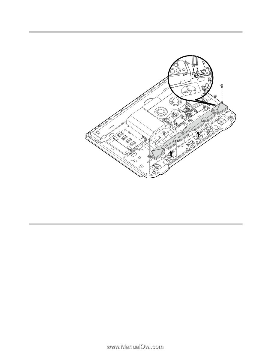
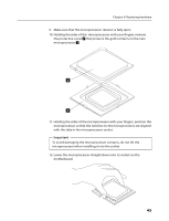
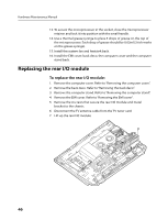
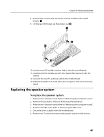
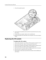
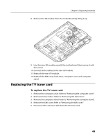
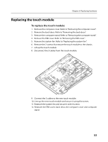
Hardware Maintenance Manual 7. Lift up the speaker system. 8. Line up the new speaker system with the chassis then secure it using the screws. 9. Connect the new speaker cables to the motherboard. 10. Reattach the EMI cover, back deco, the computer cover and computer stand. Replacing the 3D module To replace the 3D module: 1. Remove the computer cover. Refer to "Removing the computer cover". 2. Remove the back deco. Refer to "Removing the back deco". 3. Remove the computer stand. Refer to "Removing the computer stand". 4. Remove the EMI cover. Refer to "Removing the EMI cover". 5. Remove the rear I/O module. Refer to "Replacing the rear I/O module". 6. Disconnect the 3 cables from the 3D module. 7. Remove the 3 screws that secure the 3D module to the motherboard and chassis. 48
-
 1
1 -
2
-
3
-
4
-
5
-
6
-
7
-
8
-
9
-
10
-
11
-
12
-
13
-
14
-
15
-
16
-
17
-
18
-
19
-
20
-
21
-
22
-
23
-
24
-
25
-
26
-
27
-
28
-
29
-
30
-
31
-
32
-
33
-
34
-
35
-
36
-
37
-
38
-
39
-
40
-
41
-
42
-
43
-
44
-
 45
45 -
 46
46 -
 47
47 -
 48
48 -
 49
49 -
 50
50 -
 51
51 -
 52
52 -
 53
53 -
 54
54 -
 55
55 -
56
-
57
-
58
-
59
-
60
-
61
-
62
-
63
-
64
-
65
-
66
-
67
-
68
-
69
-
70
-
71
-
72
-
73
 |
 |