Lenovo ThinkPad T550 (English) Hardware Maintenance Manual - ThinkPad T550, W5 - Page 90
Keyboard assembly, Removing an LCD FRU for models without touch panel
 |
View all Lenovo ThinkPad T550 manuals
Add to My Manuals
Save this manual to your list of manuals |
Page 90 highlights
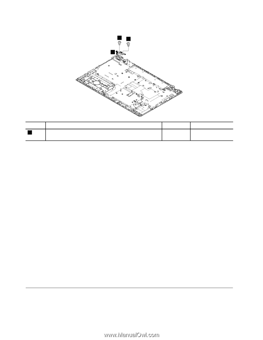
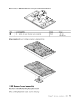
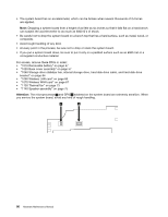
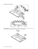
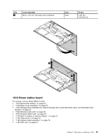
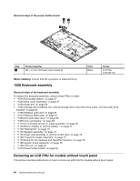
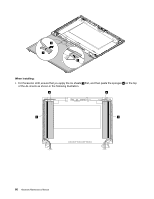
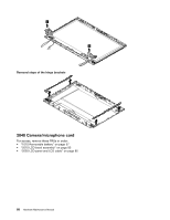
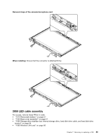
Removal steps of the power button board 11 2 Step 1 Screw (quantity) M2 × L3 mm, flat-head, nylon-coated (2) Color Black Torque 0.181 Nm (1.85 kgf-cm) When installing: Ensure that the connector is attached firmly. 1220 Keyboard assembly Removal steps of the keyboard assembly To replace the keyboard assembly, remove these FRUs in order: • "1010 Removable battery" on page 57 • "1020 Base cover assembly" on page 57 • "1030 Keyboard" on page 59 • "1040 Storage-drive stabilizer bar, internal storage drive, hard disk drive cable, and hard disk drive bracket" on page 64 • "1060 Wireless LAN card" on page 66 • "1070 Wireless WAN card" on page 67 • "1080 M.2 solid-state drive" on page 68 • "1090 Coin-cell battery" on page 69 • "1110 dc-in bracket and dc-in cable assembly" on page 70 • "1120 Built-in battery or dummy battery " on page 71 • "1130 Thermal fan" on page 73 • "1140 Speaker assembly" on page 75 • "1150 Smart card assembly or dummy smart card" on page 76 • "1160 Fingerprint reader assembly" on page 77 • "1170 Board for the trackpad and TrackPoint buttons" on page 78 • "1180 System board assembly" on page 79 • "1190 LCD unit" on page 81 • "1210 Power button board" on page 83 Removing an LCD FRU for models without touch panel This section provides instructions on how to remove an LCD FRU for models without touch panel. 84 Hardware Maintenance Manual
-
 1
1 -
2
-
3
-
4
-
5
-
6
-
7
-
8
-
9
-
10
-
11
-
12
-
13
-
14
-
15
-
16
-
17
-
18
-
19
-
20
-
21
-
22
-
23
-
24
-
25
-
26
-
27
-
28
-
29
-
30
-
31
-
32
-
33
-
34
-
35
-
36
-
37
-
38
-
39
-
40
-
41
-
42
-
43
-
44
-
45
-
46
-
47
-
48
-
49
-
50
-
51
-
52
-
53
-
54
-
55
-
56
-
57
-
58
-
59
-
60
-
61
-
62
-
63
-
64
-
65
-
66
-
67
-
68
-
69
-
70
-
71
-
72
-
73
-
74
-
75
-
76
-
77
-
78
-
79
-
80
-
81
-
82
-
83
-
84
-
 85
85 -
 86
86 -
 87
87 -
 88
88 -
 89
89 -
 90
90 -
 91
91 -
 92
92 -
 93
93 -
 94
94 -
 95
95 -
96
-
97
-
98
-
99
-
100
-
101
-
102
-
103
-
104
-
105
-
106
-
107
-
108
-
109
-
110
-
111
-
112
 |
 |