Lenovo ThinkPad T550 (English) Hardware Maintenance Manual - ThinkPad T550, W5 - Page 99
Removing an LCD FRU for models with touch panel, 3010 LCD front sheet bezel
 |
View all Lenovo ThinkPad T550 manuals
Add to My Manuals
Save this manual to your list of manuals |
Page 99 highlights
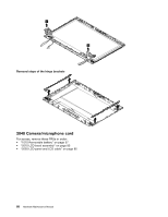
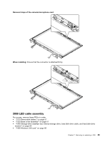
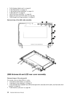
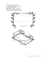
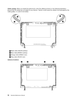
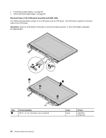
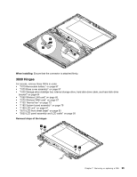
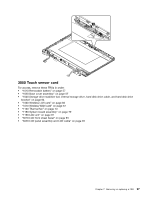
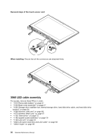
a WLAN auxiliary antenna (black) b WWAN auxiliary antenna (blue) c WWAN main antenna (red) d WLAN main antenna (gray) Removal steps of the LCD rear cover assembly To replace the LCD rear cover assembly, remove these FRUs in order: • "1010 Removable battery" on page 57 • "1020 Base cover assembly" on page 57 • "1040 Storage-drive stabilizer bar, internal storage drive, hard disk drive cable, and hard disk drive bracket" on page 64 • "1060 Wireless LAN card" on page 66 • "1070 Wireless WAN card" on page 67 • "1130 Thermal fan" on page 73 • "1180 System board assembly" on page 79 • "1190 LCD unit" on page 81 • "2010 LCD bezel assembly" on page 85 • "2020 LCD panel and LCD cable" on page 85 • "2030 Hinges and hinge brackets" on page 87 • "2040 Camera/microphone card" on page 88 • "2050 LED cable assembly" on page 89 • "Removal steps of the antenna kit" on page 90 Removing an LCD FRU for models with touch panel This section provides instructions on how to remove an LCD FRU for models with touch panel. 3010 LCD front sheet bezel Important: Once an LCD front sheet bezel is removed, it cannot be used anymore. A new LCD front sheet bezel is required for replacement. Removal steps of the LCD front sheet bezel When installing: Ensure that all the latches are attached firmly. 3020 LCD panel assembly and LCD cable For access, remove these FRUs in order: Chapter 7. Removing or replacing a FRU 93
-
 1
1 -
2
-
3
-
4
-
5
-
6
-
7
-
8
-
9
-
10
-
11
-
12
-
13
-
14
-
15
-
16
-
17
-
18
-
19
-
20
-
21
-
22
-
23
-
24
-
25
-
26
-
27
-
28
-
29
-
30
-
31
-
32
-
33
-
34
-
35
-
36
-
37
-
38
-
39
-
40
-
41
-
42
-
43
-
44
-
45
-
46
-
47
-
48
-
49
-
50
-
51
-
52
-
53
-
54
-
55
-
56
-
57
-
58
-
59
-
60
-
61
-
62
-
63
-
64
-
65
-
66
-
67
-
68
-
69
-
70
-
71
-
72
-
73
-
74
-
75
-
76
-
77
-
78
-
79
-
80
-
81
-
82
-
83
-
84
-
85
-
86
-
87
-
88
-
89
-
90
-
91
-
92
-
93
-
 94
94 -
 95
95 -
 96
96 -
 97
97 -
 98
98 -
 99
99 -
 100
100 -
 101
101 -
 102
102 -
 103
103 -
 104
104 -
105
-
106
-
107
-
108
-
109
-
110
-
111
-
112
 |
 |
