LiftMaster LA100 LA100 Linear Gate Operator Manual - Page 10
INSTALLATION, Mounting the Control Box and Power Supply
 |
View all LiftMaster LA100 manuals
Add to My Manuals
Save this manual to your list of manuals |
Page 10 highlights
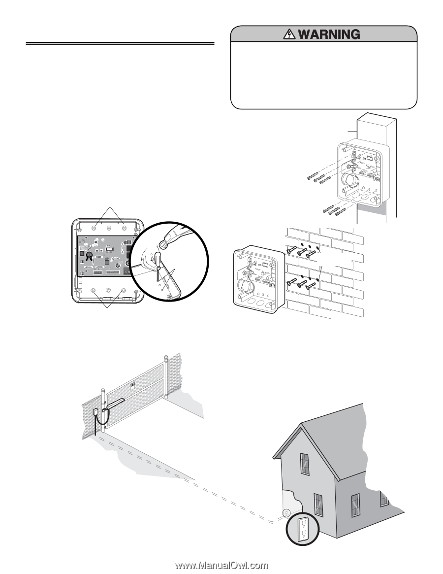
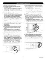
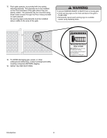
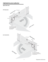
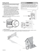
INSTALLATION Mounting the Control Box and Power Supply 1 MOUNT CONTROL BOX The recommended height for the control box is no less than 4' (1.2 m) above the ground and within 1' (.3 m) of the gate post. Do not mount control box more than 5' (1.5 m) from gate operator. PVC conduit (not provided) is recommended to be installed from the control box to the power supply location. Remove the cover screws (4) then set cover aside. Select mounting holes within the control box that is best suited for your application and knock out using a screw driver or punch. Attach the control box using the holes located within the control box and secure with appropriate hardware (Figure 1). NOTE: Be sure to clean out any debris from the control box that may have accumulated. Knock Outs To reduce the risk of electric shock, this power supply equipment has a grounding type plug, that has a grounding pin. This plug will only fit into a grounding type outlet. If the plug does not fit in the outlet, contact a qualified electrician to install the proper outlet. Do not change the plug in any way. Dry location use only. Square Gate Post Screw (not provided) Q7 Figure 1 LEARN / CLOSE MODE / OPEN ALARM RESET JU1 R17 S1 D16 C42 S2 MIN R6 C38 C98 GATE FORCE U2 U2 127A0154P6 2007 36 MAX +_ _+ IR SWITCH BLU RED WHT BRN GRN YEL 24VAC MOV1 D20 K1 K2 Knock Outs Anchors (not provided) Wall Knock Outs 2 MOUNT POWER SUPPLY The power supply provided must be located in a dry location that is protected from weather conditions, such as inside the house or garage. NOTE: Do not plug power supply in until instructed to do so. KpPtDTiMlmheEoadiEyseneoPioeswnnttvCirtttliLiehrhaIanEteonnncAusggjchtRaumeiplt!GdeirursGriysoaeaaftrrnotetueorwaoesmv.rapeereaChnsDryeiiacnaptmelgeean.oasrtahvottCeeehnaglaeytanutaternsayonerce Installation Indoor Outlet 10
-
 1
1 -
2
-
3
-
4
-
 5
5 -
 6
6 -
 7
7 -
 8
8 -
 9
9 -
 10
10 -
 11
11 -
 12
12 -
 13
13 -
 14
14 -
 15
15 -
16
-
17
-
18
-
19
-
20
-
21
-
22
-
23
-
24
-
25
-
26
-
27
-
28
-
29
-
30
-
31
-
32
 |
 |