LiftMaster LA100 LA100 Linear Gate Operator Manual - Page 20
Wiring Diagram, To protect against fire and electrocution
 |
View all LiftMaster LA100 manuals
Add to My Manuals
Save this manual to your list of manuals |
Page 20 highlights
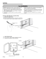
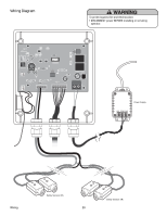
Wiring Diagram To protect against fire and electrocution: • DISCONNECT power BEFORE installing or servicing operator. Q7 C38 C98 D16 C42 S2 K2 LEARN / CLOSE MODE / OPEN MIN R17 S1 RESET JU1 R6 GATE FORCE U2 U2 127A0154P6 2007 36 MAX +_ _+ IR SWITCH BLU RED WHT BRN GRN YEL 24VAC MOV1 D20 K1 Power Supply 12V COM 24V ALARM Wiring Safety Sensors (IR) 20 Safety Sensors (IR)
-
 1
1 -
2
-
3
-
4
-
5
-
6
-
7
-
8
-
9
-
10
-
11
-
12
-
13
-
14
-
 15
15 -
 16
16 -
 17
17 -
 18
18 -
 19
19 -
 20
20 -
 21
21 -
 22
22 -
 23
23 -
 24
24 -
 25
25 -
26
-
27
-
28
-
29
-
30
-
31
-
32
 |
 |

12V
COM
24V
YEL
MOV1
LEARN / CLOSE
MODE / OPEN
RESET
ALARM
JU1
R17
S1
S2
C38
C98
U2
U2
C42
D16
R6
Q7
SWITCH
24VAC
IR
+
+
_
_
GRN
BRN
WHT
RED
BLU
K2
K1
D20
127A0154P6
2007
36
GATE
FORCE
MAX
MIN
Wiring Diagram
Wiring
20
Safety Sensors (IR)
Safety Sensors (IR)
To protect against fire and electrocution:
•
DISCONNECT power BEFORE installing or servicing
operator.
Power Supply