LiftMaster LA100 LA100 Linear Gate Operator Manual - Page 24
Safety Sensor Connections, RESET BUTTON, TIMER TO CLOSE TTC
 |
View all LiftMaster LA100 manuals
Add to My Manuals
Save this manual to your list of manuals |
Page 24 highlights
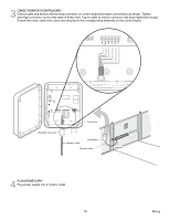
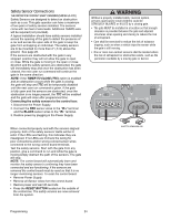
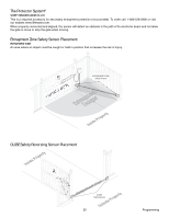
Safety Sensor Connections THE PROTECTOR SYSTEM® SAFETY SENSORS (MODEL 50-220) Safety Sensors are designed to detect an obstruction such as a car. This gate operator can have a maximum of two pairs of safety sensors installed. The sensors come with two feet of wire leads. Additional 16AWG wire will be required (not provided). A typical installation should have safety sensors installed across the opening of the gate to detect the presence of a car and across the open side of the gate to keep the gate from entrapping an individual. The safety sensors are to be mounted no more than 2" (.6 m) above the ground. See page 25. If the sensors are obstructed with the gate in any stopped position they will not allow the gate to open or close. While the gate is moving in the open or close direction and the safety sensors are obstructed, the gate will immediately stop and once the obstruction has been cleared, the next user run command will continue the gate in the same direction. NOTE: If the TIMER TO CLOSE (TTC) option is enabled and an obstruction occurs while the gate is closing, the gate will stop and TTC will be temporarily disabled until the next user run command is given. If the gate is fully open and the sensors are obstructed, once the obstruction is no longer present, the TTC will be enabled and the gate will close after programmed time. Connecting the safety sensors to the control box: 1. Disconnect the Power Supply. 2. Connect the RED sensor wires to the "IR+" terminal and the BLACK sensor wires to the "IR-" terminal. 3. Restore power by plugging in the Power Supply. Without a properly installed safety reversal system, persons (particularly small children) could be SERIOUSLY INJURED or KILLED by a closing gate. • The gate MUST be installed in a location so that enough clearance is provided between the gate and adjacent structures when opening and closing to reduce the risk of entrapment. • Care shall be exercised to reduce the risk of nuisance tripping, such as when a vehicle trips the sensor while the gate is still moving. • One or more non-contact sensors shall be located where the risk of entrapment or obstruction exists, such as the perimeter reachable by a moving gate or barrier. R6 R17 RESET JU1 ALARM +_ _+ IR SWITCH +_ _+ IR SWITCH When connected properly and with the sensors aligned properly, both of the safety sensors' LEDs will be lit solid. If the LEDs are flashing, this indicates they are misaligned. If no LEDs are lit check the wiring for poor connections and/or wrong colored sensor wires connected to the wrong control board terminals. Test the safety sensors. Start with the gate from any position, give a command to run and while the gate is moving simply obstruct the path of the sensors. The gate will stop. NOTE: The control board will automatically learn and monitor the safety sensor's confirming they have been connected and are functioning. if the sensors are removed the control board must be reset so that it is no longer monitoring sensors. To reset the control board: • Remove Power Supply. • Remove all Sensor wires from the control board. • Restore power and wait 30 seconds. • Press the RESET BUTTON located on the outside of the control box. The safety sensors are now removed from the system. SAFETY SENSORS (IR) BRN GRN YEL Programming 24
-
 1
1 -
2
-
3
-
4
-
5
-
6
-
7
-
8
-
9
-
10
-
11
-
12
-
13
-
14
-
15
-
16
-
17
-
18
-
 19
19 -
 20
20 -
 21
21 -
 22
22 -
 23
23 -
 24
24 -
 25
25 -
 26
26 -
 27
27 -
 28
28 -
 29
29 -
30
-
31
-
32
 |
 |