LiftMaster LA100 LA100 Linear Gate Operator Manual - Page 4
Additional Items For Purchase, Tools Needed, Distance from indoor AC, Outlet to Control Box
 |
View all LiftMaster LA100 manuals
Add to My Manuals
Save this manual to your list of manuals |
Page 4 highlights
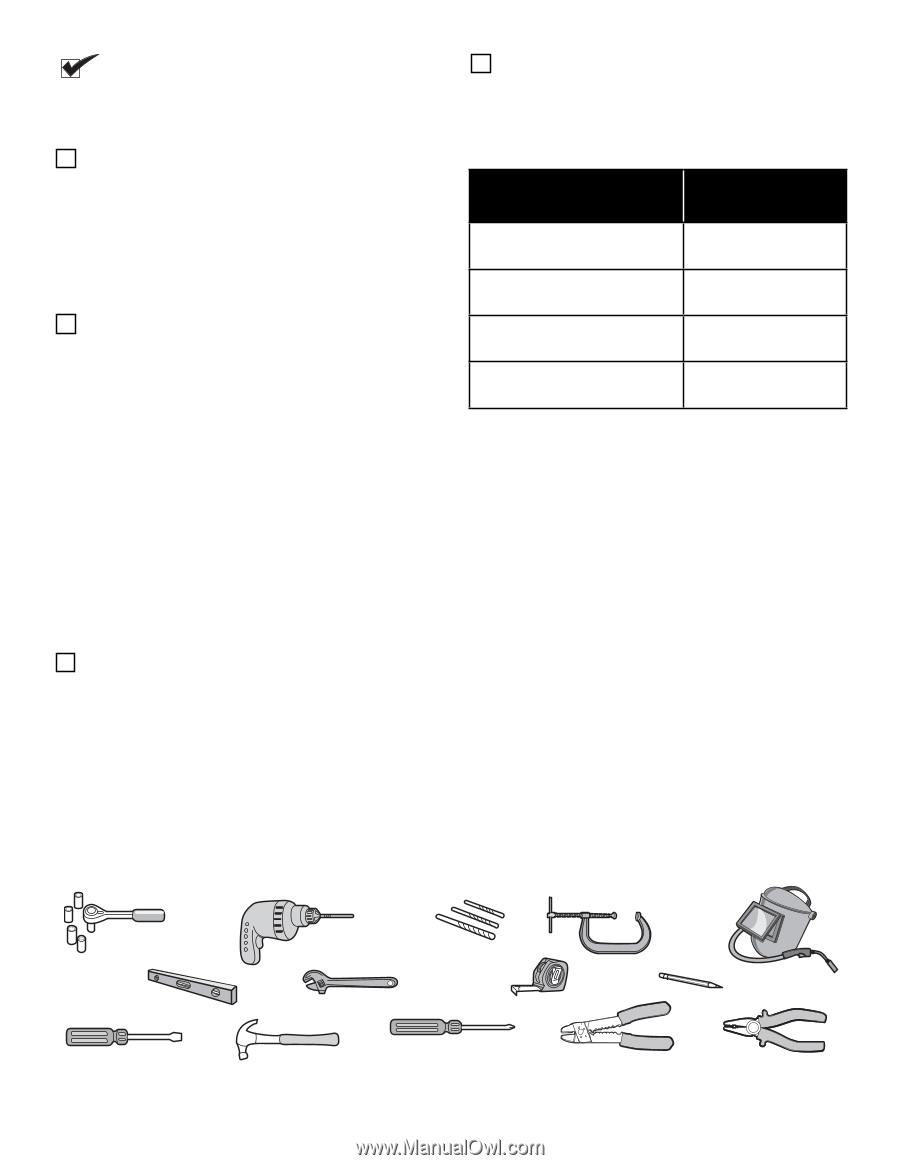
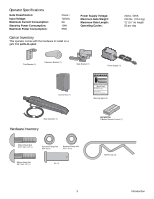
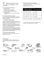
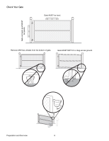
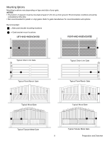
Additional Items For Purchase The following items are REQUIRED to complete the installation: CONTROL BOX MOUNTING HARDWARE • Mounting to Wood: Four #8 x 1-1/2" wood screws • Mounting to Brick/Cement/Masonry: Four 1/4" masonry screws 1-3/4" long • Mounting to Metal: Four #10-32 machine screws with washers and lock nuts GATE BRACKET MOUNTING HARDWARE For 1 or 2 inch circular or square tubular constructed gates, use the following U-bolts with associated flat washers and hex nuts: • 1" use 5/16-18 x 2-3/16" U-bolt (2) • 2" use 5/16-18 x 3-3/16" U-bolt (2) To secure the bracket to the gate, use the following hardware: 1/4-20 x 3" hex head bolt with associated flat washers, lock washers and hex nuts (2). For gates with flat mounting surfaces and a maximum thickness 2", an alternate to using U-bolts would be: 5/16-18 x 3" hex head bolt with associated flat washers, lock washers and hex head nuts (4). For chain link fences or other types with circular rails, it is best to attach a vertical support panel connecting the top rail to the bottom rail. The gate bracket can then be mounted to this vertical panel using the same bolts, washers and nuts as mentioned above. POST BRACKET MOUNTING HARDWARE Two 3/8-16 x 6" carriage bolts with flat washers, lock washers and lock nuts. THE PROTECTOR SYSTEM® SAFETY SENSORS Two pair of UL listed, outdoor, infrared safety sensors. • LiftMaster Model 50-220 See page 25 for more information. Distance from indoor AC Outlet to Control Box Wire Gauge Needed 100 ft. (30.5 m) or less 16 gauge 100 - 150 ft. (30.5 - 45.7 m) 14 gauge* 150 - 250 ft. (45.7 - 76.2 m) 12 gauge* 250 ft. (76.2 m) and above Not Recommended * UL Listed, Stranded, Direct Burial, UV Resistant Wire Installed per the National Electric Code, NEC. Tools Needed During assembly, installation and adjustment of the operator, instructions will call for tools as illustrated below. Deep Well Sockets and Wrench 1/2", 5/8", 7/16", 9/16" and 1/4" Carpenter's Level Screwdriver Drill Adjustable End Wrench Drill Bits 1/2", 3/16", 5/16" and 5/32" 1 2 Tape Measure Clamps Pencil Welder (Optional) Hammer Phillips Head Screwdriver Wire Strippers (Optional) Wire Cutters (Optional) Introduction 4
-
 1
1 -
 2
2 -
 3
3 -
 4
4 -
 5
5 -
 6
6 -
 7
7 -
 8
8 -
 9
9 -
 10
10 -
11
-
12
-
13
-
14
-
15
-
16
-
17
-
18
-
19
-
20
-
21
-
22
-
23
-
24
-
25
-
26
-
27
-
28
-
29
-
30
-
31
-
32
 |
 |