MSI K9NU User Guide - Page 17
on the cooler set to the hooks on
 |
View all MSI K9NU manuals
Add to My Manuals
Save this manual to your list of manuals |
Page 17 highlights
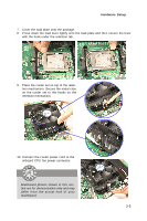
Hardware Setup 7. Cover the load plate onto the package. 8. Press down the load lever lightly onto the load plate and then secure the lever with the hook under the retention tab. 9. Place the cooler set on top of the retention mechanism. Secure the metal clips on the cooler set to the hooks on the retention mechanism. 10. Connect the cooler power cord to the onboard CPU fan power connector. Mainboard photos shown in this section are for demonstration only and may differ from the actual look of your mainboard. 2-5
-
 1
1 -
2
-
3
-
4
-
5
-
6
-
7
-
8
-
9
-
10
-
11
-
 12
12 -
 13
13 -
 14
14 -
 15
15 -
 16
16 -
 17
17 -
 18
18 -
 19
19 -
 20
20 -
 21
21 -
 22
22 -
23
-
24
-
25
-
26
-
27
-
28
-
29
-
30
-
31
-
32
-
33
-
34
-
35
-
36
-
37
-
38
-
39
-
40
-
41
-
42
-
43
-
44
-
45
-
46
-
47
-
48
-
49
-
50
-
51
-
52
-
53
-
54
-
55
-
56
-
57
-
58
-
59
-
60
-
61
-
62
-
63
-
64
-
65
-
66
-
67
-
68
-
69
-
70
-
71
-
72
-
73
-
74
-
75
-
76
-
77
-
78
-
79
-
80
-
81
-
82
-
83
-
84
-
85
-
86
-
87
-
88
-
89
-
90
-
91
-
92
-
93
-
94
-
95
-
96
-
97
-
98
-
99
-
100
-
101
-
102
-
103
-
104
-
105
-
106
 |
 |

2-5
Hardware Setup
7.
Cover the load plate onto the package.
8.
Press down the load lever lightly onto the load plate and then secure the lever
with the hook under the retention tab.
9.
Place the cooler set on top of the reten-
tion mechanism. Secure the metal clips
on the cooler set to the hooks on the
retention mechanism.
10. Connect the cooler power cord to the
onboard CPU fan power connector.
Mainboard photos shown in this sec-
tion are for demonstration only and may
differ from the actual look of your
mainboard.