MSI K9NU User Guide - Page 21
Power Supply
 |
View all MSI K9NU manuals
Add to My Manuals
Save this manual to your list of manuals |
Page 21 highlights
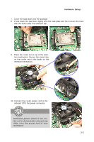
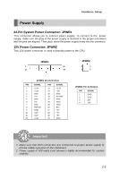
Hardware Setup Power Supply 24-Pin System Power Connector: JPWR1 This connector allows you to connect power supply. To connect to the power supply, make sure the plug of the power supply is inserted in the proper orientation and the pins are aligned. Then push down the power supply firmly into the connector. 12V Power Connector: JPWR2 This 12V power connector is used to provide power to the CPU. JPWR1 1 12 13 24 JPWR2 3 4 1 2 JPWR1 Pin Definition PIN SIGNAL 1 +3.3V 2 +3.3V 3 GND 4 +5V 5 GND 6 +5V 7 GND 8 PW R OK 9 5VSB 10 +12V 11 +12V 12 +3.3V PIN SIGNAL 13 +3.3V 14 -12V 15 GND 16 PS-ON# 17 GND 18 GND 19 GND 20 Res 21 +5V 22 +5V 23 +5V 24 GND JPWR2 Pin Definition PIN SIGNAL 1 GND 2 GND 3 12V 4 12V Important 1. Make sure that both connectors are connected to proper power supply to ensure stable operation of the mainboard. 2. Power supply of 600 watts (and above) is highly recommended for system stability. 2-9
-
 1
1 -
2
-
3
-
4
-
5
-
6
-
7
-
8
-
9
-
10
-
11
-
12
-
13
-
14
-
15
-
 16
16 -
 17
17 -
 18
18 -
 19
19 -
 20
20 -
 21
21 -
 22
22 -
 23
23 -
 24
24 -
 25
25 -
 26
26 -
27
-
28
-
29
-
30
-
31
-
32
-
33
-
34
-
35
-
36
-
37
-
38
-
39
-
40
-
41
-
42
-
43
-
44
-
45
-
46
-
47
-
48
-
49
-
50
-
51
-
52
-
53
-
54
-
55
-
56
-
57
-
58
-
59
-
60
-
61
-
62
-
63
-
64
-
65
-
66
-
67
-
68
-
69
-
70
-
71
-
72
-
73
-
74
-
75
-
76
-
77
-
78
-
79
-
80
-
81
-
82
-
83
-
84
-
85
-
86
-
87
-
88
-
89
-
90
-
91
-
92
-
93
-
94
-
95
-
96
-
97
-
98
-
99
-
100
-
101
-
102
-
103
-
104
-
105
-
106
 |
 |
