MSI K9NU User Guide - Page 25
Serial ATA II Connector: SATA 1 / 2 / 3 / 4 / 5 / 6 Optional, SAS Connector: SASC1, SASC2 Optional,
 |
View all MSI K9NU manuals
Add to My Manuals
Save this manual to your list of manuals |
Page 25 highlights
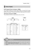
Hardware Setup SAS Connector: SASC1, SASC2 (Optional) These connectors are designed to connect Serial ATA devices only. SAS LED Connector: J10, J11 (Optional) These connectors are used to connect external LEDs to show the status of the SATA HDDs attached to the SASC1 & SASC2. The J10 is intended for the SASC1 and the J11 is made for the SASC2. W hen a SATA HDD is attached to the SAS connector, the LED connecting pin 1 & 2 will glow. W hen HDD activity/access is detected, the LED connecting pin 3 & 4 will blink. SASC1/2 J10/J11 1 Pin Definition PIN SIGNAL 1 +3.3V 2 GND 3 +3.3V 4 SATA Read Serial ATA II Connector: SATA 1 / 2 / 3 / 4 / 5 / 6 (Optional) These connectors are high-speed Serial ATA II interface ports. Each connector can connect one Serial ATA II device. SATA6 SATA5 SATA4 SATA3 SATA2 SATA1 Important Please do not fold the Serial ATA cable into 90-degree angle. Otherwise, data loss may occur during transmission. 2-13
-
 1
1 -
2
-
3
-
4
-
5
-
6
-
7
-
8
-
9
-
10
-
11
-
12
-
13
-
14
-
15
-
16
-
17
-
18
-
19
-
 20
20 -
 21
21 -
 22
22 -
 23
23 -
 24
24 -
 25
25 -
 26
26 -
 27
27 -
 28
28 -
 29
29 -
 30
30 -
31
-
32
-
33
-
34
-
35
-
36
-
37
-
38
-
39
-
40
-
41
-
42
-
43
-
44
-
45
-
46
-
47
-
48
-
49
-
50
-
51
-
52
-
53
-
54
-
55
-
56
-
57
-
58
-
59
-
60
-
61
-
62
-
63
-
64
-
65
-
66
-
67
-
68
-
69
-
70
-
71
-
72
-
73
-
74
-
75
-
76
-
77
-
78
-
79
-
80
-
81
-
82
-
83
-
84
-
85
-
86
-
87
-
88
-
89
-
90
-
91
-
92
-
93
-
94
-
95
-
96
-
97
-
98
-
99
-
100
-
101
-
102
-
103
-
104
-
105
-
106
 |
 |
