Marantz UD5005 UD5005 User Manual - English - Page 46
Rear panel
 |
View all Marantz UD5005 manuals
Add to My Manuals
Save this manual to your list of manuals |
Page 46 highlights
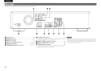
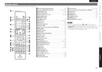
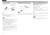
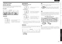
ENGLISH Rear panel For buttons not explained here, see the page indicated in parentheses ( ). Q0 oi q w e r t y u q AC inlet (AC IN 5) w N ETWORK connector 27) e HDMI OUT connector 4) r DIGITAL OUT COAXIAL connector 10, 12) t VIDEO OUT connector 9, 10, 11) y COMPONENT VIDEO OUT connectors 9, 10, 11) u 2ch AUDIO OUT connectors 11) For software recorded in multi-channel, analog signals that have been down-mixed into 2 channels are output. i REMOTE CONTROL IN/OUT connectors 28) o REMOTE CONTROL INT./EXT. switch 28) Q0 FLASHER IN/OUT connectors 28) Connect an external control device or other device for servicing. (Use a straight cable for the connection.) NOTE • Do not touch the inner pins of the connectors on the rear panel. Electrostatic discharge may cause permanent damage to the unit. • Do not put your finger or foreign object in the fan opening. Doing so could cause injury or unit failure. 42
-
 1
1 -
2
-
3
-
4
-
5
-
6
-
7
-
8
-
9
-
10
-
11
-
12
-
13
-
14
-
15
-
16
-
17
-
18
-
19
-
20
-
21
-
22
-
23
-
24
-
25
-
26
-
27
-
28
-
29
-
30
-
31
-
32
-
33
-
34
-
35
-
36
-
37
-
38
-
39
-
40
-
 41
41 -
 42
42 -
 43
43 -
 44
44 -
 45
45 -
 46
46 -
 47
47 -
 48
48 -
 49
49 -
 50
50 -
 51
51 -
52
-
53
-
54
-
55
-
56
-
57
-
58
-
59
-
60
-
61
-
62
-
63
-
64
-
65
-
66
-
67
-
68
-
69
-
70
-
71
-
72
 |
 |
