Maytag MGC4436BDC Installation Manual - Page 4
Connecting, Appliance, Supply - appliances
 |
UPC - 883049142012
View all Maytag MGC4436BDC manuals
Add to My Manuals
Save this manual to your list of manuals |
Page 4 highlights
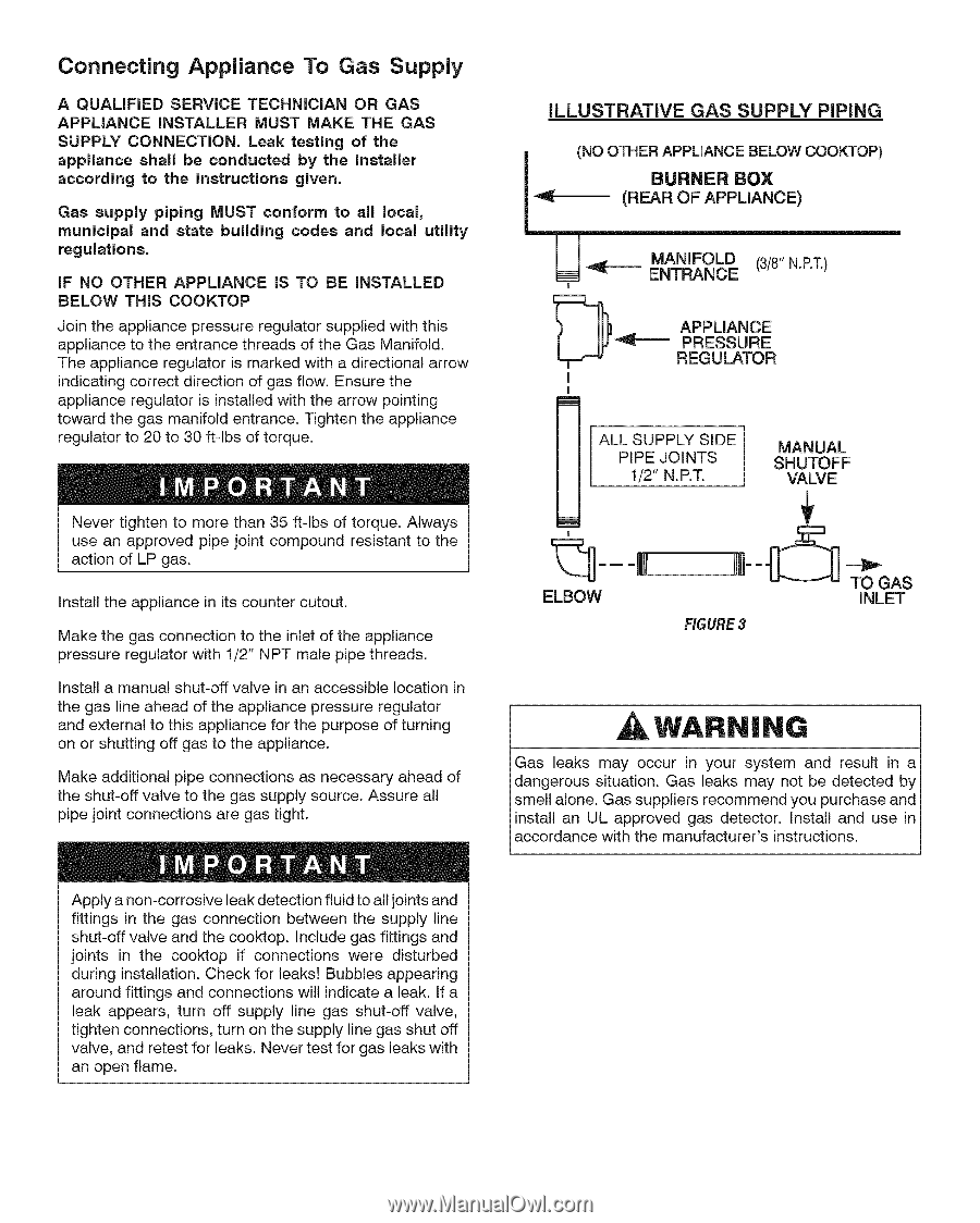
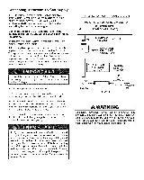
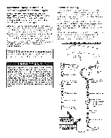
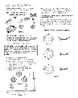
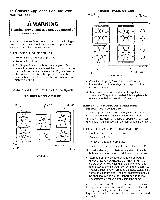
Connecting Appliance To Gas Supply A QUALIFIED SERVICE TECHNiCiAN OR GAS APPLIANCE iNSTALLER MUST MAKE THE GAS SUPPLY CONNECTION. Leak testing of the appliance shall be conducted by the installer according to the instructions given. Gas supply piping MUST conform to all local, municipal and state building codes and local utility regulations. IF NO OTHER APPLIANCE IS TO BE iNSTALLED BELOW THIS COOKTOP Join the appliance pressure regulator supplied with this appliance to the entrance threads of the Gas Manifold. The appliance regulator is marked with a directional arrow indicating correct direction of gas flow. Ensure the appliance regulator is installed with the arrow pointing toward the gas manifold entrance. Tighten the appliance regulator to 20 to 30 ft-lbs of torque. Never tighten to more than 35 ft-lbs of torque. Always use an approved pipe joint compound resistant to the action of LP gas. Install the appliance in its counter cutout. Make the gas connection to the inlet of the appliance pressure regulator with 1/2" NPT male pipe threads. Install a manual shut-off valve in an accessible location in the gas line ahead of the appliance pressure regulator and external to this appliance for the purpose of turning on or shutting off gas to the appliance. Make additional pipe connections as necessary ahead of the shut-off valve to the gas supply source. Assure all pipe joint connections are gas tight. iLLUSTRATiVE GAS SUPPLY PiPiNG (NO OTHER APPLIANCE BELOW COOKTOP) BURNER BOX U EMNATNRIFAONLCDE (3/8"N.P.T.) I I_ _ , I I APPRPESLSIAUNRCEE REGULATOR ALL SUPPLY SIDE PIPE JOINTS 1/2" N.P.T. MANUAL SHUTOFF VALVE =T- ELBOW FIGURE3 TO GAS iNLET WARNING Gas leaks may occur in your system and result in a dangerous situation. Gas leaks may not be detected by smell alone. Gas suppliers recommend you purchase and install an UL approved gas detector. Install and use in accordance with the manufacturer's instructions. Apply a non-corrosive leak detection fluid to all joints and fittings in the gas connection between the supply line shut-off valve and the cooktop. Include gas fittings and joints in the cooktop if connections were disturbed during installation. Check for leakst Bubbles appearing around fittings and connections will indicate a leak. If a leak appears, turn off supply line gas shut-off valve, tighten connections, turn on the supply line gas shut off valve, and retest for leaks. Never test for gas leaks with an open flame.
-
 1
1 -
 2
2 -
 3
3 -
 4
4 -
 5
5 -
 6
6 -
 7
7 -
 8
8 -
 9
9 -
 10
10 -
11
-
12
-
13
-
14
-
15
-
16
-
17
-
18
-
19
-
20
-
21
-
22
-
23
-
24
-
25
-
26
-
27
-
28
-
29
-
30
-
31
-
32
-
33
 |
 |