Maytag MGC4436BDC Installation Manual - Page 9
To Convert, Appliance, Natural - knobs
 |
UPC - 883049142012
View all Maytag MGC4436BDC manuals
Add to My Manuals
Save this manual to your list of manuals |
Page 9 highlights
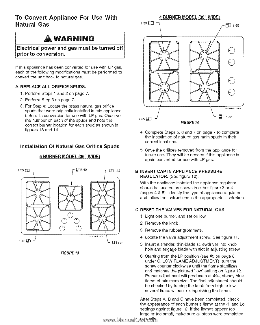
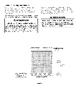
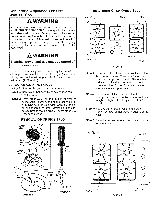
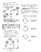
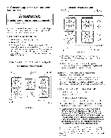
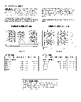
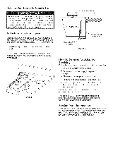
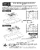
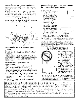
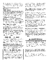
To Convert Appliance For Use With Natural Gas WARNING Electrical power and gas must be turned off prior to conversion. If this appliance has been converted for use with LP gas, each of the following modifications must be performed to convert the unit back to natural gas. A. REPLACE ALL ORIFICE SPUDS. 1. Perform Steps 1 and 2 on page 7. 2. Perform Step 3 on page 7. 3. For Step 4: Locate the brass natural gas orifice spuds that were originally installed in this appliance before its conversion for use with LP gas. Observe the number on each of the spuds and note the correct burner location for each spud as shown in figures 13 and 14. installation Of Natural Gas Orifice Spuds 5 BURNER MODEL (36" WIDE[ 1.55I_ - _]1.42 _] 1.42 1.42I_ 0 00 00 FIGURE 13 _- _] 1.61 4 BURNER MODEL (30" WIDE[ 155_L] --_ f _[_] 1.55 0 0 0 0 155_ J FIGURE 14 ART,S2 a5- a_3- I1 _] 1.85 4. Complete Steps 5, 6 and 7 on page 7 to complete the installation of natural gas main spuds in their correct locations. 5. Save the orifices removed from the appliance for future use. They will be needed if this appliance is again converted for use with LP gas. B. INVERT CAP IN APPLIANCE PRESSURE REGULATOR. (See figure 10). With the appliance installed the appliance regulator should be located as shown in either figure 3 or 4 (pages 4 & 5). Identify the type of appliance regulator and follow the instructions in the appropriate illustration. C. RESET THE VALVES FOR NATURAL GAS 1. Light one burner, and set on low. 2. Remove the knob. , Remove the rubber grommets. 4. Locate the valve adjustment screw. See figure 11. 5. Insert a slender, thin-blade screwdriver into knob hole and engage blade with slot in adjusting screw. , Starting from the LP position (see #5 on page 8, under C. LOW FLAME ADJUSTMENT), turn the screw counter clockwise until the flame stabilizes and matches the pictured "low" setting on figure 12. Proper adjustment will produce a stable, steady blue flame of minimum size. The final adjustment should be checked by turning the knob from high to low several times without extinguishing the flame. After Steps A, B and C have been completed, check the appearance of each burner's flame at the Hi and Lo settings against figure 12. If the flames appear too large or too small, make sure all steps were completed correctly.
-
 1
1 -
2
-
3
-
 4
4 -
 5
5 -
 6
6 -
 7
7 -
 8
8 -
 9
9 -
 10
10 -
 11
11 -
 12
12 -
 13
13 -
 14
14 -
15
-
16
-
17
-
18
-
19
-
20
-
21
-
22
-
23
-
24
-
25
-
26
-
27
-
28
-
29
-
30
-
31
-
32
-
33
 |
 |