Motorola 8900 User Manual - Page 47
UIM Interface, UIM Connection
 |
UPC - 845374028836
View all Motorola 8900 manuals
Add to My Manuals
Save this manual to your list of manuals |
Page 47 highlights
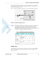
Chapter 2: Hardware Interface Description UIM Interface The C24 incorporates a UIM interface, which conforms to the ISO/IEC 7816 standard which defines the electrical, signaling and protocol specifications of a UIM card. C24 does not incorporate an on-board UIM card tray for UIM placement. The UIM must be located on the user application board, external to the C24. The C24 UIM interface includes all the necessary signals, which are routed to the interface connector, for a direct and complete connection to an external UIM. C24 supports dynamic detection of the UIM card, through a dedicated UIM detection signal. C24 will detect a UIM card insertion or removal upon power up or during operation by the transitions on the UIM_PD_N signal. Important: The UIM interface can't be operated together with the UART2 interface. Both interfaces share the same internal HW port. Therefore, applications using the UIM interface must not connect any external devices to the UART2 interface, and vise versa. UIM Connection Figure 2-13 illustrates a typical UIM interface connection to C24. This connection type is implemented on the C24 Developer Board, using an FCI SIM tray, PN 7111S1615A05. Figure 2-13: C24 UIM Interface December 15, 2008 C24 Module Hardware Description 23
-
 1
1 -
2
-
3
-
4
-
5
-
6
-
7
-
8
-
9
-
10
-
11
-
12
-
13
-
14
-
15
-
16
-
17
-
18
-
19
-
20
-
21
-
22
-
23
-
24
-
25
-
26
-
27
-
28
-
29
-
30
-
31
-
32
-
33
-
34
-
35
-
36
-
37
-
38
-
39
-
40
-
41
-
 42
42 -
 43
43 -
 44
44 -
 45
45 -
 46
46 -
 47
47 -
 48
48 -
 49
49 -
 50
50 -
 51
51 -
 52
52 -
53
-
54
-
55
-
56
-
57
-
58
-
59
-
60
-
61
-
62
-
63
-
64
-
65
-
66
-
67
-
68
-
69
-
70
-
71
-
72
-
73
-
74
-
75
-
76
-
77
-
78
-
79
-
80
-
81
-
82
-
83
-
84
-
85
-
86
-
87
-
88
-
89
-
90
-
91
-
92
-
93
-
94
-
95
-
96
-
97
-
98
 |
 |
