Motorola 8900 User Manual - Page 55
Digital Audio Interface, Table 2-9: Alert Port Specifications, Parameter, Conditions
 |
UPC - 845374028836
View all Motorola 8900 manuals
Add to My Manuals
Save this manual to your list of manuals |
Page 55 highlights
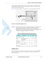
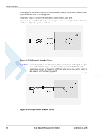
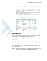
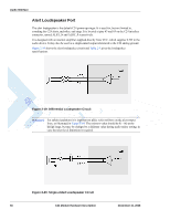
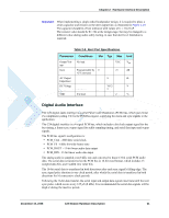
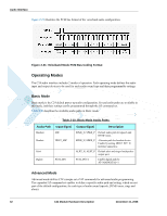
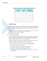
Chapter 2: Hardware Interface Description Important: When implementing a single ended loudspeaker design, it is required to place a series capacitor and resistor on the alert output line, as illustrated in Figure 2-20. The capacitor should be of low tolerance with values of C = 10-22 uF. The resistor value should be R = 0Ω at the design stage, but may be changed to a different value during audio safety testing, in case that alert level limitation is required. Table 2-9: Alert Port Specifications Parameter Conditions Min Typ Max Output Voltage Gain AC Output Impedance DC Voltage No load Programmable by 0 AT Command THD 8 Ω load VCC 21 8 VCC/ 2 2 Unit Vpp dB Ω V % Digital Audio Interface The C24 digital audio interface is a serial Pulse Code Modulation (PCM) bus, which uses linear 2's compliment coding. C24 is the PCM bus master, supplying the clock and sync signals to the application. The C24 digital interface is a 4 signal PCM bus, which includes a bit clock output signal for the bus timing, a frame sync output signal for audio sampling timing, and serial data input and output signals. The PCM bus signal's configuration is: • PCM_CLK - 2048 kHz serial clock • PCM_FS - 8 kHz bit-wide frame-sync • PCM_DOUT - 13-bit linear audio data output • PCM_DIN - 13-bit linear audio data input The analog audio is sampled at an 8 kHz rate and converted to linear 13-bit serial PCM audio data. The serial data is transferred on the PCM bus in 16-bit word format, which includes 13 sampled data bits, and 3 added zero value bits. The 16-bit serial data is transferred in both directions after each sync signal's falling edge. The sync signal pulse duration is one clock period, after which the serial data is transferred in both directions for 16 consecutive clock periods. Following the 16-bit data transfer, the serial input and output data signals inactivate until the next sync pulse, which occurs every 125 µS (8 kHz). It is recommended the serial data signals will be High-Z during the inactive period. December 15, 2008 C24 Module Hardware Description 31
-
 1
1 -
2
-
3
-
4
-
5
-
6
-
7
-
8
-
9
-
10
-
11
-
12
-
13
-
14
-
15
-
16
-
17
-
18
-
19
-
20
-
21
-
22
-
23
-
24
-
25
-
26
-
27
-
28
-
29
-
30
-
31
-
32
-
33
-
34
-
35
-
36
-
37
-
38
-
39
-
40
-
41
-
42
-
43
-
44
-
45
-
46
-
47
-
48
-
49
-
 50
50 -
 51
51 -
 52
52 -
 53
53 -
 54
54 -
 55
55 -
 56
56 -
 57
57 -
 58
58 -
 59
59 -
 60
60 -
61
-
62
-
63
-
64
-
65
-
66
-
67
-
68
-
69
-
70
-
71
-
72
-
73
-
74
-
75
-
76
-
77
-
78
-
79
-
80
-
81
-
82
-
83
-
84
-
85
-
86
-
87
-
88
-
89
-
90
-
91
-
92
-
93
-
94
-
95
-
96
-
97
-
98
 |
 |
