Motorola 8900 User Manual - Page 62
A/D Interface, General Purpose A/D, Power Supply A/D
 |
UPC - 845374028836
View all Motorola 8900 manuals
Add to My Manuals
Save this manual to your list of manuals |
Page 62 highlights
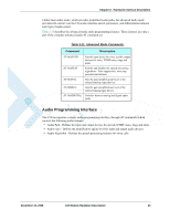
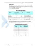
A/D Interface A/D Interface The C24 includes 4 Analog to Digital Converter (ADC) signals with 8-bit resolution, for environmental and electrical measurements. The ADC signals measure an analog DC voltage level on their inputs which is converted to an 8-bit digital value for further processing by C24 or the user application. The A/D signals operation and reporting mechanism is defined by the AT+MMAD command. Table 2-16 below, lists the internal and external A/D signals provided by C24. Table 2-16: A/D Signals ADC Name Description VCC ADC3 ADC2 ADC1 Power Supply A/D GPAD 3 GPAD 2 GPAD 1 ADC Pin # # Min Max Unit - 5 47 3 43 2 37 1 3.0 4.5 V 0.1 2.5 V 0.1 2.5 V 0.1 2.5 V General Purpose A/D The C24 provides 3 general purpose A/D (GPAD) signals for customer application use. Each A/D signal can monitor a separate external voltage and report its measured level independently to the application, through the AT command interface. The GPAD signals measure a DC voltage level of 0.1 - 2.5 V, which is converted internally to a 8-bit digital value. The user application can monitor the A/D voltage level through the AT+MMAD command, which returns the measured DC level in Volts times 100. For example, a measured analog DC level of 1.75 Volts will be presented as 175 by the MMAD command. Table 2-17 gives the GPAD specifications. Table 2-17: GPAD Specifications Parameter Conditions Maximum Operating range Input Voltage Measurement ADC range Voltage Resolution Min Typ Max Unit 0 2.75 V 0.1 2.5 V 10 mV Power Supply A/D The main power supply (VCC) is constantly monitored internally by the C24 through a dedicated A/D signal, which is not accessible on the interface connector. 38 C24 Module Hardware Description December 15, 2008
-
 1
1 -
2
-
3
-
4
-
5
-
6
-
7
-
8
-
9
-
10
-
11
-
12
-
13
-
14
-
15
-
16
-
17
-
18
-
19
-
20
-
21
-
22
-
23
-
24
-
25
-
26
-
27
-
28
-
29
-
30
-
31
-
32
-
33
-
34
-
35
-
36
-
37
-
38
-
39
-
40
-
41
-
42
-
43
-
44
-
45
-
46
-
47
-
48
-
49
-
50
-
51
-
52
-
53
-
54
-
55
-
56
-
 57
57 -
 58
58 -
 59
59 -
 60
60 -
 61
61 -
 62
62 -
 63
63 -
 64
64 -
 65
65 -
 66
66 -
 67
67 -
68
-
69
-
70
-
71
-
72
-
73
-
74
-
75
-
76
-
77
-
78
-
79
-
80
-
81
-
82
-
83
-
84
-
85
-
86
-
87
-
88
-
89
-
90
-
91
-
92
-
93
-
94
-
95
-
96
-
97
-
98
 |
 |
