Motorola 8900 User Manual - Page 60
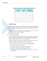
Audio Design, Table 2-15, Microphone and Headset Microphone Port Gains, AT Command, Value, Gain Level
 |
UPC - 845374028836
View all Motorola 8900 manuals
Add to My Manuals
Save this manual to your list of manuals |
Page 60 highlights
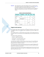
Audio Interface . Table 2-15: Microphone and Headset Microphone Port Gains AT Command Value 0 ... 3 ... 16 ... 31 Gain Level (dB) 9 ... 12 ... 25 ... 36 Maximum Input Level (mVRMS) 350 ... 250 ... 55 ... 11 Audio Design The audio quality delivered by C24 is highly affected by the application audio design, particularly when using the analog audio interface. Therefore, special care must be taken when designing the C24 audio interface. Improper design and implementation of the audio interface will result in poor audio quality. Poor audio quality is a result of electrical interferences, or noises, from circuits surrounding the audio interface. There are several possible sources for the audio noise: • Transients and losses on the power supply • EMI from antenna radiations • Digital logic switching noise Most of the audio noise originates from the DC supply current, which appear on the main power supply lines and antenna, but also indirectly penetrate the internal application's supplies and signals. The noises are transferred into the C24's audio circuits through the microphone input signals and then are amplified by the C24's internal audio amplifiers. To minimize the audio noise and improve the audio performance the microphone and speaker signals must be designed with sufficient protection from surrounding noises. The following guidelines should be followed to achieve best audio performance: • Reference the microphone & speaker circuits to the C24 AGND interface signal. • Keep the audio circuits away from the antenna. • Use RF filtering capacitors on the audio signals, as described in Table 2-3. • The audio signals should not be routed adjacent to digital signals. • Isolate the audio signals by a surrounding ground plane or shields. • Filter internal supplies and signals that may indirectly affect the audio circuits, from noises and voltage drops. 36 C24 Module Hardware Description December 15, 2008
-
 1
1 -
2
-
3
-
4
-
5
-
6
-
7
-
8
-
9
-
10
-
11
-
12
-
13
-
14
-
15
-
16
-
17
-
18
-
19
-
20
-
21
-
22
-
23
-
24
-
25
-
26
-
27
-
28
-
29
-
30
-
31
-
32
-
33
-
34
-
35
-
36
-
37
-
38
-
39
-
40
-
41
-
42
-
43
-
44
-
45
-
46
-
47
-
48
-
49
-
50
-
51
-
52
-
53
-
54
-
 55
55 -
 56
56 -
 57
57 -
 58
58 -
 59
59 -
 60
60 -
 61
61 -
 62
62 -
 63
63 -
 64
64 -
 65
65 -
66
-
67
-
68
-
69
-
70
-
71
-
72
-
73
-
74
-
75
-
76
-
77
-
78
-
79
-
80
-
81
-
82
-
83
-
84
-
85
-
86
-
87
-
88
-
89
-
90
-
91
-
92
-
93
-
94
-
95
-
96
-
97
-
98
 |
 |
