Motorola 8900 User Manual - Page 48
UIM Design Guidelines, Table 2-5, Interface Signals, Signal Name, Description
 |
UPC - 845374028836
View all Motorola 8900 manuals
Add to My Manuals
Save this manual to your list of manuals |
Page 48 highlights
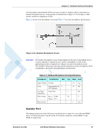
UIM Interface Table 2-5 details the UIM interface signals. Table 2-5: UIM Interface Signals Pin # 48 44 52 46 50 Signal Name UIM_VCC UIM_RST_N UIM_DIO UIM_CLK UIM_PD_N Description 2.85V Supply to the UIM Active low reset signal Serial input and output data Serial 3.25 MHz clock Active low card presence detection UIM Design Guidelines The UIM interface and signals design is important for proper operation of C24 and the UIM card. Below are several design guidelines that must be followed to achieve a robust and stable design that meets the required standards and regulations. • Two 100nF low ESR capacitors must be placed, in parallel, on the UIM_VCC signal line. The capacitors should be located as near as possible to the UIM card tray contacts. The capacitors value may slightly change depending on the application design. • A 56Ω series resistor must be placed on the UIM_DIO signal line. The resistor value may slightly change depending on the application design. • A 100Ω series resistor must be placed on the UIM_CLK signal line. The resistor value may slightly change depending on the application design. • It is recommended to design component placeholders (unpopulated) for capacitors on the UIM_RST and UIM_DIO signal lines. • The UIM card tray should be located, and its signals should be routed, away from any possible EMI sources, such as the RF and digital switching signals. • The UIM interface signals length should not exceed 100mm between the C24 interface connector and the UIM tray. • The UIM clock and data signals (UIM_CLK and UIM_DIO) should be routed separately on the application board, and preferably isolated by a surrounding ground plane. • In case that transient suppressors (zener diodes, etc.) are used by the application on the UIM card signals, individual package components (not arrays) with low capacitance should be used. • The C24 interface does not support UIM programming through the VPP signal. This signal should not be connected to C24. • Using the UIM detection signal (UIM_PD_N) is mandatory in case that the UIM card is accessible to the user, and may be removed during C24 operation. To avoid damage to the UIM or C24, the UIM interface signals must be deactivated before the UIM card is mechanically removed from the UIM tray contacts. Therefore, the UIM_PD_N detection signal must be disabled before the UIM is removed from the tray. 24 C24 Module Hardware Description December 15, 2008
-
 1
1 -
2
-
3
-
4
-
5
-
6
-
7
-
8
-
9
-
10
-
11
-
12
-
13
-
14
-
15
-
16
-
17
-
18
-
19
-
20
-
21
-
22
-
23
-
24
-
25
-
26
-
27
-
28
-
29
-
30
-
31
-
32
-
33
-
34
-
35
-
36
-
37
-
38
-
39
-
40
-
41
-
42
-
 43
43 -
 44
44 -
 45
45 -
 46
46 -
 47
47 -
 48
48 -
 49
49 -
 50
50 -
 51
51 -
 52
52 -
 53
53 -
54
-
55
-
56
-
57
-
58
-
59
-
60
-
61
-
62
-
63
-
64
-
65
-
66
-
67
-
68
-
69
-
70
-
71
-
72
-
73
-
74
-
75
-
76
-
77
-
78
-
79
-
80
-
81
-
82
-
83
-
84
-
85
-
86
-
87
-
88
-
89
-
90
-
91
-
92
-
93
-
94
-
95
-
96
-
97
-
98
 |
 |
