Motorola 8900 User Manual - Page 49
Audio Interface, Handset Microphone Port
 |
UPC - 845374028836
View all Motorola 8900 manuals
Add to My Manuals
Save this manual to your list of manuals |
Page 49 highlights
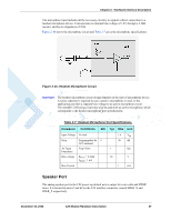
Chapter 2: Hardware Interface Description Audio Interface The C24 audio interface supports several audio devices and operating modes. The audio interface's operating modes, active devices, amplification levels and speech processing algorithms are fully controlled by the host application, through advanced programming options and a versatile AT commands set. The C24 supports the following audio devices: • Two single-ended and biased analog microphone inputs for use in a variety of modes. • Two differential analog speaker outputs for use in a variety of modes. • A digital serial interface using PCM coding. Figure 2-14 shows the audio interface topology. Figure 2-14: Audio Interface Topology Handset Microphone Port The handset microphone port is the C24 power-up default active audio input for voice calls. It is located on pin 61 at the C24 interface connector, named MIC. It is designed as a single-ended input and should be referenced to the C24 analog ground. The microphone input includes all the necessary circuitry to support a direct connection to an external microphone device. It incorporates an internal bias voltage of 1.8V through a 2.2kΩ resistor, and has an impedance of 1kΩ. December 15, 2008 C24 Module Hardware Description 25
-
 1
1 -
2
-
3
-
4
-
5
-
6
-
7
-
8
-
9
-
10
-
11
-
12
-
13
-
14
-
15
-
16
-
17
-
18
-
19
-
20
-
21
-
22
-
23
-
24
-
25
-
26
-
27
-
28
-
29
-
30
-
31
-
32
-
33
-
34
-
35
-
36
-
37
-
38
-
39
-
40
-
41
-
42
-
43
-
 44
44 -
 45
45 -
 46
46 -
 47
47 -
 48
48 -
 49
49 -
 50
50 -
 51
51 -
 52
52 -
 53
53 -
 54
54 -
55
-
56
-
57
-
58
-
59
-
60
-
61
-
62
-
63
-
64
-
65
-
66
-
67
-
68
-
69
-
70
-
71
-
72
-
73
-
74
-
75
-
76
-
77
-
78
-
79
-
80
-
81
-
82
-
83
-
84
-
85
-
86
-
87
-
88
-
89
-
90
-
91
-
92
-
93
-
94
-
95
-
96
-
97
-
98
 |
 |
