Motorola 8900 User Manual - Page 56
Operating Modes, Basic Mode, Advanced Mode, Voiceband Mode PCM Bus Coding Format
 |
UPC - 845374028836
View all Motorola 8900 manuals
Add to My Manuals
Save this manual to your list of manuals |
Page 56 highlights
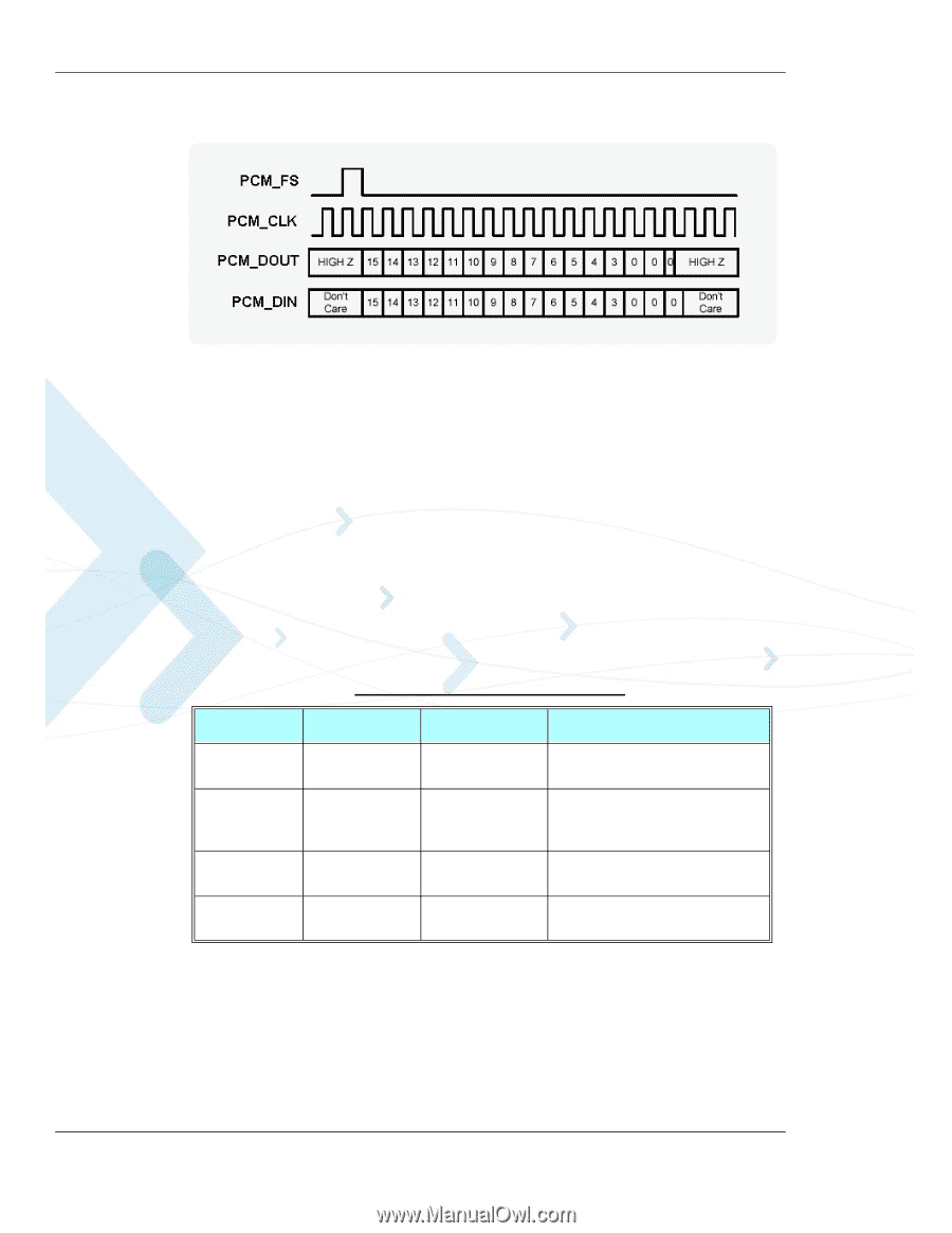
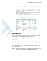
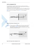
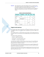
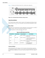
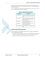
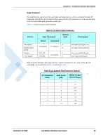
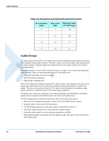
Audio Interface Figure 2-21 illustrates the PCM bus format of the voiceband audio configuration. Figure 2-21: Voiceband Mode PCM Bus Coding Format Operating Modes The C24 audio interface includes 2 modes of operation. Each operating mode defines the audio input and output devices to be used for each audio sound type and their programmable settings. Basic Mode Basic mode is the C24 default power-up audio configuration. Several audio paths are available in this mode, and their settings can be programmed through the AT command set. Table 2-10 describes the available audio paths in Basic mode. Table 2-10: Basic Mode Audio Paths Audio Path Input Signal Output Signal Description Handset Headset Alert Digital MIC HDST_MIC PCM_DIN SPKR_N, SPKR_P Default audio path for speech and DTMF tones. SPKR_N, SPKR_P Alternate path for headset device. Enable by setting HDST_INT_N interface signal low. ALRT_N, ALRT_P Default alert and ringer loudspeaker output port. PCM_DOUT Enable digital path by AT+MADIGITAL=1 Advanced Mode Advanced mode utilizes C24's unique set of AT commands for advanced audio programming. The expanded AT command set enables to define a specific audio path and setting, which are not part of the default configuration, for each type of audio sound (speech, DTMF tones, rings and alerts). 32 C24 Module Hardware Description December 15, 2008
-
 1
1 -
2
-
3
-
4
-
5
-
6
-
7
-
8
-
9
-
10
-
11
-
12
-
13
-
14
-
15
-
16
-
17
-
18
-
19
-
20
-
21
-
22
-
23
-
24
-
25
-
26
-
27
-
28
-
29
-
30
-
31
-
32
-
33
-
34
-
35
-
36
-
37
-
38
-
39
-
40
-
41
-
42
-
43
-
44
-
45
-
46
-
47
-
48
-
49
-
50
-
 51
51 -
 52
52 -
 53
53 -
 54
54 -
 55
55 -
 56
56 -
 57
57 -
 58
58 -
 59
59 -
 60
60 -
 61
61 -
62
-
63
-
64
-
65
-
66
-
67
-
68
-
69
-
70
-
71
-
72
-
73
-
74
-
75
-
76
-
77
-
78
-
79
-
80
-
81
-
82
-
83
-
84
-
85
-
86
-
87
-
88
-
89
-
90
-
91
-
92
-
93
-
94
-
95
-
96
-
97
-
98
 |
 |