Motorola 8900 User Manual - Page 51
Speaker Port, Headset Microphone Circuit, Table 2-7
 |
UPC - 845374028836
View all Motorola 8900 manuals
Add to My Manuals
Save this manual to your list of manuals |
Page 51 highlights
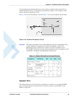
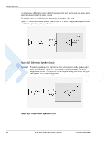
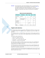
Chapter 2: Hardware Interface Description The microphone input includes all the necessary circuitry to support a direct connection to a headset microphone device. It incorporates an internal bias voltage of 1.8V through a 2.2kΩ resistor, and has an impedance of 1kΩ. Figure 2-16 shows the microphone circuit and Table 2-7 gives the microphone specifications. Figure 2-16: Headset Microphone Circuit Important: The headset microphone circuit design depends on the type of microphone device. A series capacitor is required in case a passive microphone is used, or the application provides a separate bias voltage to an active microphone circuit. The internal C24 biasing circuit may also be used with an active microphone, which corresponds to the headset microphone port specifications. Table 2-7: Headset Microphone Port Specifications Parameter Conditions Min Typ Max Unit Input Voltage No load Gain AC Input Impedance Bias voltage Bias Current Programmable by 9 AT Command Freq=1Khz RBIAS = 2.2 kΩ IBIAS < 1 mA 1.6 Vpp 36 dB 1 kΩ 1.8 V 1 mA Speaker Port The analog speaker port is the C24 power-up default active output for voice calls and DTMF tones. It is located at pins 67 and 69 on the C24 interface connector, named SPKR_N and SPKR_P respectively. December 15, 2008 C24 Module Hardware Description 27
-
 1
1 -
2
-
3
-
4
-
5
-
6
-
7
-
8
-
9
-
10
-
11
-
12
-
13
-
14
-
15
-
16
-
17
-
18
-
19
-
20
-
21
-
22
-
23
-
24
-
25
-
26
-
27
-
28
-
29
-
30
-
31
-
32
-
33
-
34
-
35
-
36
-
37
-
38
-
39
-
40
-
41
-
42
-
43
-
44
-
45
-
 46
46 -
 47
47 -
 48
48 -
 49
49 -
 50
50 -
 51
51 -
 52
52 -
 53
53 -
 54
54 -
 55
55 -
 56
56 -
57
-
58
-
59
-
60
-
61
-
62
-
63
-
64
-
65
-
66
-
67
-
68
-
69
-
70
-
71
-
72
-
73
-
74
-
75
-
76
-
77
-
78
-
79
-
80
-
81
-
82
-
83
-
84
-
85
-
86
-
87
-
88
-
89
-
90
-
91
-
92
-
93
-
94
-
95
-
96
-
97
-
98
 |
 |
