Motorola 8900 User Manual - Page 65
Wakeup Out, VREF Power-up Timing, Table 2-20, VREF Specifications, Parameter, Conditions
 |
UPC - 845374028836
View all Motorola 8900 manuals
Add to My Manuals
Save this manual to your list of manuals |
Page 65 highlights
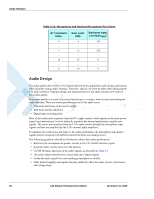
Chapter 2: Hardware Interface Description Important: The VREF regulator is powered from the C24's main power supply, and therefore any current sourced through this regulator originates from the C24 VCC supply. The overall VCC current consumed by C24 is directly affected by the VREF operation. The C24 current consumption rises with respect to the current sourced through VREF. Figure 2-23 shows the VREF power-up timing. Figure 2-23: VREF Power-up Timing Table 2-20 gives the VREF specifications. Table 2-20: VREF Specifications Parameter Conditions VOUT IOUT Load regulation Line regulation PSRR IOUT < 150 mA 20 Hz - 20 kHz Min Typ Max Unit -4% 2.8 +4% V 150 mA 0.65 mV/ mA 2.8 mV 21 dB Wakeup Out Some applications incorporate their own power saving mode, in which they operate with minimal functionality, including disabling of interfaces and serial communications. The wakeup-out (WKUPO_N) signal is an active low output, which is designed to support a low power mode feature in the host application. This signal is used by C24 to indicate that it requires to communicate with the host application through the serial interface, due to an incoming call or data, or an unsolicited event. Applications that incorporate a low power mode should use this December 15, 2008 C24 Module Hardware Description 41
-
 1
1 -
2
-
3
-
4
-
5
-
6
-
7
-
8
-
9
-
10
-
11
-
12
-
13
-
14
-
15
-
16
-
17
-
18
-
19
-
20
-
21
-
22
-
23
-
24
-
25
-
26
-
27
-
28
-
29
-
30
-
31
-
32
-
33
-
34
-
35
-
36
-
37
-
38
-
39
-
40
-
41
-
42
-
43
-
44
-
45
-
46
-
47
-
48
-
49
-
50
-
51
-
52
-
53
-
54
-
55
-
56
-
57
-
58
-
59
-
 60
60 -
 61
61 -
 62
62 -
 63
63 -
 64
64 -
 65
65 -
 66
66 -
 67
67 -
 68
68 -
 69
69 -
 70
70 -
71
-
72
-
73
-
74
-
75
-
76
-
77
-
78
-
79
-
80
-
81
-
82
-
83
-
84
-
85
-
86
-
87
-
88
-
89
-
90
-
91
-
92
-
93
-
94
-
95
-
96
-
97
-
98
 |
 |
