Netgear FSM7328PS FSM7328PS Hardware manual - Page 16
FSM7352PS Front Panel and LEDs, Table 2-4. FSM7352S LED Description
 |
UPC - 606449051810
View all Netgear FSM7328PS manuals
Add to My Manuals
Save this manual to your list of manuals |
Page 16 highlights
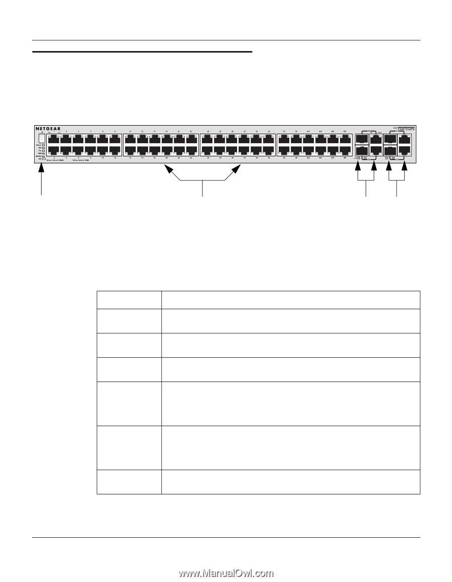
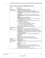
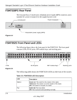
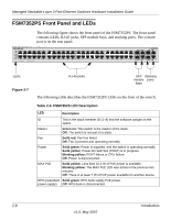
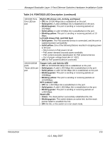
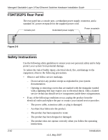
Managed Stackable Layer 3 Fast Ethernet Switches Hardware Installation Guide FSM7352PS Front Panel and LEDs The following figure shows the front panel of the FSM7352PS. The front panel contains LEDs, RJ-45 jacks, SFP module bays, and stacking ports. The console port is on the rear panel. FSM7352PS Front Panel 1 LEDs Figure 2-7 RJ-45 jacks SFP Stacking module ports bays The following table describes the FSM7352PS LEDs on the front of the switch. Table 2-4. FSM7352S LED Description LED Description ID This is the stack member ID (1-8) that the software assigns to the switch. Master Green on: This switch is the master of the stack. Off: The switch is not part of a stack. Fan Solid red: Fan has failed. Off: Fan is present and operating normally. Power Solid green: Power is supplied, and the switch is operating normally. Solid yellow: Power-On Self-Test (POST) is in progress. Blinking yellow: POST failure or CPU failure. Off: Power is disconnected. MAX PoE Solid yellow: Less than 15.4 W of PoE power is available. Blinking yellow: The MAX PoE LED was active in the previous two minutes. Off: There is at least 7 W of PoE power available for another device. RPS (redundant Solid green: RPS bank supply PoE power. power supply) Off: RPS bank is disconnected. 2-8 Introduction v1.0, May 2007
-
 1
1 -
2
-
3
-
4
-
5
-
6
-
7
-
8
-
9
-
10
-
 11
11 -
 12
12 -
 13
13 -
 14
14 -
 15
15 -
 16
16 -
 17
17 -
 18
18 -
 19
19 -
 20
20 -
 21
21 -
22
-
23
-
24
-
25
-
26
-
27
-
28
-
29
-
30
-
31
-
32
-
33
-
34
-
35
-
36
-
37
-
38
-
39
-
40
-
41
-
42
 |
 |