Netgear FSM7328PS FSM7328PS Hardware manual - Page 26
Check the Installation, Connect to Power and Check the LEDs, see Troubleshooting.
 |
UPC - 606449051810
View all Netgear FSM7328PS manuals
Add to My Manuals
Save this manual to your list of manuals |
Page 26 highlights
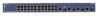
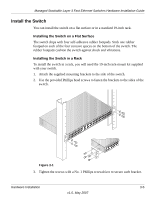
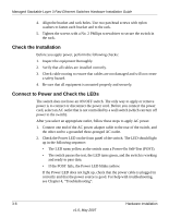
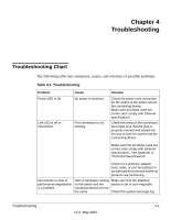
Managed Stackable Layer 3 Fast Ethernet Switches Hardware Installation Guide 4. Align the bracket and rack holes. Use two pan-head screws with nylon washers to fasten each bracket and to the rack. 5. Tighten the screws with a No. 2 Phillips screwdriver to secure the switch in the rack. Check the Installation Before you apply power, perform the following checks: 1. Inspect the equipment thoroughly. 2. Verify that all cables are installed correctly. 3. Check cable routing to ensure that cables are not damaged and will not create a safety hazard. 4. Be sure that all equipment is mounted properly and securely. Connect to Power and Check the LEDs The switch does not have an ON/OFF switch. The only way to apply or remove power is to connect or disconnect the power cord. Before you connect the power cord, select an AC outlet that is not controlled by a wall switch (which can turn off power to the switch). After you select an appropriate outlet, follow these steps to apply AC power. 1. Connect one end of the AC power adapter cable to the rear of the switch, and the other end to a grounded three-pronged AC outlet. 2. Check the Power LED on the front panel of the switch. The LED should light up in the following sequence: • The LED turns yellow as the switch runs a Power-On Self-Test (POST). • The switch passes the test, the LED turns green, and the switch is working and ready to pass data. • If the POST fails, the Power LED blinks yellow. If the Power LED does not light up, check that the power cable is plugged in correctly and that the power source is good. For help with troubleshooting, see Chapter 4, "Troubleshooting". 3-6 Hardware Installation v1.0, May 2007
-
 1
1 -
2
-
3
-
4
-
5
-
6
-
7
-
8
-
9
-
10
-
11
-
12
-
13
-
14
-
15
-
16
-
17
-
18
-
19
-
20
-
 21
21 -
 22
22 -
 23
23 -
 24
24 -
 25
25 -
 26
26 -
 27
27 -
 28
28 -
 29
29 -
 30
30 -
 31
31 -
32
-
33
-
34
-
35
-
36
-
37
-
38
-
39
-
40
-
41
-
42
 |
 |