Netgear FSM7328PS FSM7328PS Hardware manual - Page 24
Select a Location, Table 3-1. Site Requirements for Switch Location
 |
UPC - 606449051810
View all Netgear FSM7328PS manuals
Add to My Manuals
Save this manual to your list of manuals |
Page 24 highlights
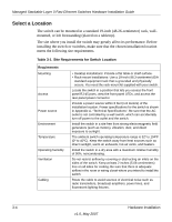
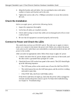
Managed Stackable Layer 3 Fast Ethernet Switches Hardware Installation Guide Select a Location The switch can be mounted in a standard 19-inch (48.26-centimeter) rack, wallmounted, or left freestanding (placed on a tabletop). The site where you install the switch may greatly affect its performance. Before installing the switch or switches, make sure that the chosen installation location meets the following site requirements. Table 3-1. Site Requirements for Switch Location Requirements Mounting Access Power source Environment Temperature Operating humidity Ventilation Cabling • Desktop installations: Provide a flat table or shelf surface. • Rack-mount installations: Use a 19-inch (48.3-centimeter) EIA standard equipment rack that is grounded and physically secure. You need the rack-mount kit supplied with your switch. Locate the switch in a position that lets you access the front panel RJ-45 ports, view the front panel LEDs, and access the rear-panel power connector. Provide a power source within 6 feet (1.8 meters) of the installation location. Power specifications for the switch is shown in Appendix A, "Technical Specifications". Be sure that the AC outlet is not controlled by a wall switch, which can accidentally turn off power to the outlet and the switch. Install the switch in a site free from strong electromagnetic field generators (such as motors), vibration, dust, and direct exposure to sunlight. The ambient switch operating temperature range is 32º to 104ºF (0º to 40ºC). Keep the switch away from heat sources such as direct sunlight, warm air exhausts, hot-air vents, and heaters. Install the switch in a dry area with a maximum relative humidity of 90%, noncondensing. Do not restrict airflow by covering or obstructing air inlets on the sides of the switch. Keep at least 2 inches (5.08 centimeters) free on all sides for cooling. Be sure that there is adequate airflow in the room or wiring closet where you intend to install the switch. Route the cable to avoid sources of electrical noise such as radio transmitters, broadcast amplifiers, power lines, and fluorescent lighting fixtures. 3-4 Hardware Installation v1.0, May 2007
-
 1
1 -
2
-
3
-
4
-
5
-
6
-
7
-
8
-
9
-
10
-
11
-
12
-
13
-
14
-
15
-
16
-
17
-
18
-
 19
19 -
 20
20 -
 21
21 -
 22
22 -
 23
23 -
 24
24 -
 25
25 -
 26
26 -
 27
27 -
 28
28 -
 29
29 -
30
-
31
-
32
-
33
-
34
-
35
-
36
-
37
-
38
-
39
-
40
-
41
-
42
 |
 |