Netgear FSM7328PS FSM7328PS Hardware manual - Page 17
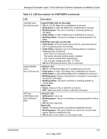
Table 2-4. FSM7352S LED Description, continued
 |
UPC - 606449051810
View all Netgear FSM7328PS manuals
Add to My Manuals
Save this manual to your list of manuals |
Page 17 highlights
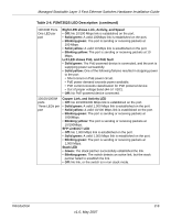
Managed Stackable Layer 3 Fast Ethernet Switches Hardware Installation Guide Table 2-4. FSM7352S LED Description (continued) 10/100M Ports One LED per port Right LED shows Link, Activity, and Speed • Off: No 10/100 Mbps link is established on the port. • Solid green: A valid 100Mbps link is established on the port. • Blinking green: The port is sending or receiving packets at 100 Mbps. • Solid yellow: A valid 10 Mbps link is established on the port. • Blinking yellow: The port is sending or receiving packets at 10 Mbps. Left LED shows PoE, and PoE fault • Solid green: The PoE-powered device is connected, and the port is supplying power successfully. • Solid yellow: One of the following failures resulted in stopping power to the port: • Short circuit on PoE power circuit. • PoE power demand exceeds power available. • PoE current exceeds classification for PoE powered device. • Out of proper voltage band (44-57 VDC). • Off: No PoE-powered device connected. 10/100/1000M ports Three LEDs per port Copper Link, and Activity LED • Off: No 10/100/1000 Mbps link is established on the port. • Solid green: A valid 1,000 Mbps link is established on the port. • Solid yellow: A valid 10/100 Mbps link is established on the port. • Blinking green: The port is sending or receiving packets at 1000Mbps. • Blinking yellow: The port is sending or receiving packets at 10/100Mbps. SFP Link/ACT LED • Off: No 1,000 Mbps link is established on the port. • Solid green: A valid 1,000 Mbps link is established on the port. • Blinking green: The port is sending or receiving packets at 1,000 Mbps. Stack LED • Green: The stack partner successfully established the link. • Blinking green: The switch detects an active link, but the stack partner failed to establish the link. • Off: No link, or the switch is in non-stack mode. Introduction 2-9 v1.0, May 2007
-
 1
1 -
2
-
3
-
4
-
5
-
6
-
7
-
8
-
9
-
10
-
11
-
 12
12 -
 13
13 -
 14
14 -
 15
15 -
 16
16 -
 17
17 -
 18
18 -
 19
19 -
 20
20 -
 21
21 -
 22
22 -
23
-
24
-
25
-
26
-
27
-
28
-
29
-
30
-
31
-
32
-
33
-
34
-
35
-
36
-
37
-
38
-
39
-
40
-
41
-
42
 |
 |