Netgear GSM7248R GSM7224R / GSM7248R Hardware Installation Guide - Page 12
GSM7224R Rear Panel, GSM7248R Front Panel and LEDs, USB port, a RST reset button, RJ-45 jacks
 |
View all Netgear GSM7248R manuals
Add to My Manuals
Save this manual to your list of manuals |
Page 12 highlights
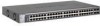
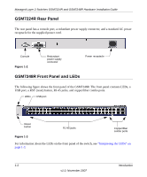
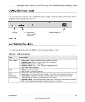
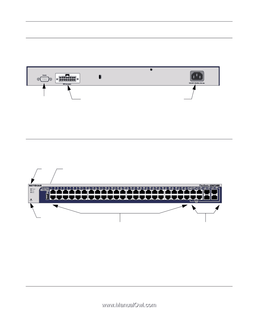
Managed Layer 2 Switches GSM7224R and GSM7248R Hardware Installation Guide GSM7224R Rear Panel The rear panel has a console port, a redundant power supply connector, and a standard AC power receptacle for the supplied power cord. Console Figure 1-2 Redundant power supply connector Power receptacle GSM7248R Front Panel and LEDs The following figure shows the front panel of the GSM7248R. The front panel contains LEDs, a USB port, a RST (reset) button, RJ-45 jacks, and copper/fiber combo ports. LEDs USB port Reset button Figure 1-3 RJ-45 jacks Copper/fiber combo ports For information about the LEDs on the front panel of the switch, see "Interpreting the LEDs" on page 1-3. 1-2 Introduction v1.0, November 2007
-
 1
1 -
2
-
3
-
4
-
5
-
6
-
 7
7 -
 8
8 -
 9
9 -
 10
10 -
 11
11 -
 12
12 -
 13
13 -
 14
14 -
 15
15 -
 16
16 -
 17
17 -
18
-
19
-
20
-
21
-
22
-
23
-
24
-
25
-
26
-
27
-
28
-
29
-
30
-
31
-
32
-
33
-
34
 |
 |
Managed Layer 2 Switches GSM7224R and GSM7248R Hardware Installation Guide
1-2
Introduction
v1.0, November 2007
GSM7224R Rear Panel
The rear panel has a console port, a redundant power supply connector, and a standard AC power
receptacle for the supplied power cord.
GSM7248R Front Panel and LEDs
The following figure shows the front panel of the GSM7248R. The front panel contains LEDs, a
USB port, a RST (reset) button, RJ-45 jacks, and copper/fiber combo ports.
For information about the LEDs on the front panel of the switch, see
“Interpreting the LEDs” on
page 1-3
.
Figure 1-2
Figure 1-3
Power receptacle
Console
Redundant
power supply
connector
Reset
LEDs
USB port
RJ-45 jacks
Copper/fiber
combo ports
button