Netgear GSM7248R GSM7224R / GSM7248R Hardware Installation Guide - Page 13
GSM7248R Rear Panel, Interpreting the LEDs, Table 1-1., LED Descriptions
 |
View all Netgear GSM7248R manuals
Add to My Manuals
Save this manual to your list of manuals |
Page 13 highlights
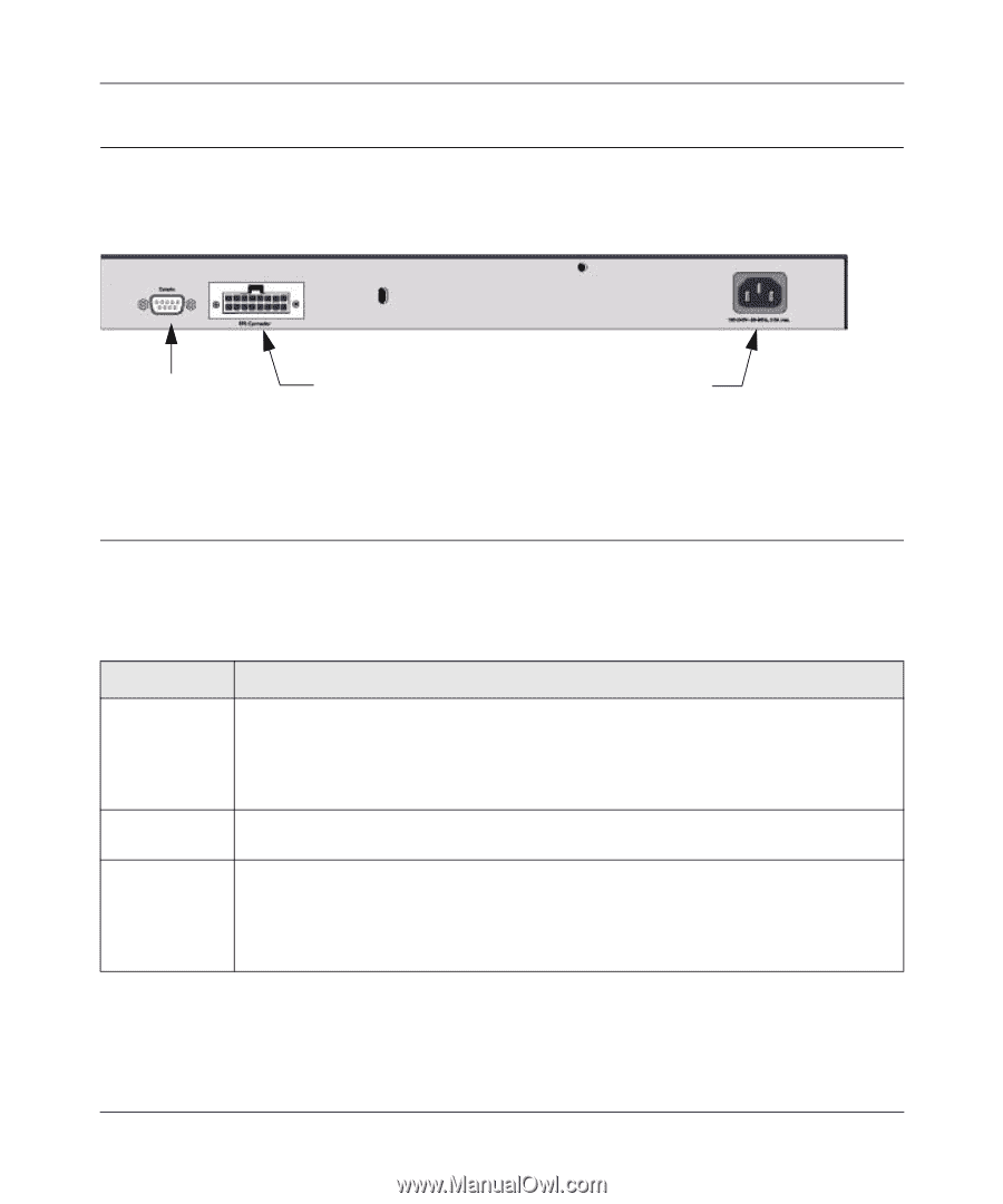
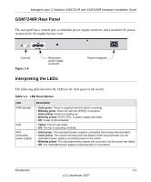
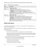
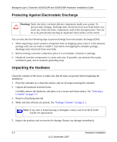
Managed Layer 2 Switches GSM7224R and GSM7248R Hardware Installation Guide GSM7248R Rear Panel The rear panel has a console port, a redundant power supply connector, and a standard AC power receptacle for the supplied power cord. Console Figure 1-4 Redundant power supply connector Interpreting the LEDs Power receptacle The following table describes the LEDs on the front panel of the switch. Table 1-1. LED Descriptions LED PWR (power) FAN RPS (redundant power supply) Description • Solid green. Power is supplied and the switch is working. • Blinking green. Power-on self-test (POST) in progress. • Solid yellow. System is booting up. • Blinking yellow. POST, CPU, or power supply has failed • Off. Power is disconnected. • Yellow. The fan has failed. • Off. The fan is operating normally. • Solid green. The redundant power supply is connected (and using internal power). • Solid yellow. The switch internal power has failed or been disconnected, but the redundant power supply is providing power to the switch. • Blinking yellow. The redundant power supply unit is present, but the power has failed. • Off. The redundant power supply is disconnected or not present. Introduction 1-3 v1.0, November 2007
-
 1
1 -
2
-
3
-
4
-
5
-
6
-
7
-
 8
8 -
 9
9 -
 10
10 -
 11
11 -
 12
12 -
 13
13 -
 14
14 -
 15
15 -
 16
16 -
 17
17 -
 18
18 -
19
-
20
-
21
-
22
-
23
-
24
-
25
-
26
-
27
-
28
-
29
-
30
-
31
-
32
-
33
-
34
 |
 |