Netgear GSM7248R GSM7224R / GSM7248R Hardware Installation Guide - Page 20
Installing the Switch, Installing the Switch on a Flat Surface
 |
View all Netgear GSM7248R manuals
Add to My Manuals
Save this manual to your list of manuals |
Page 20 highlights
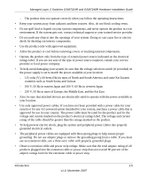
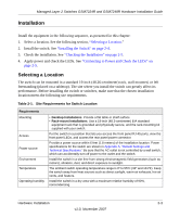
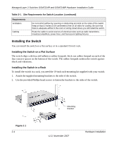
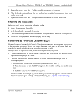
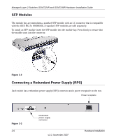
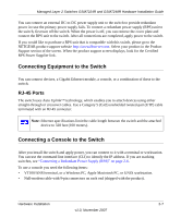
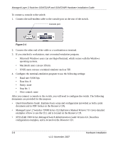
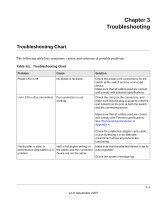
Managed Layer 2 Switches GSM7224R and GSM7248R Hardware Installation Guide Table 2-1. Site Requirements for Switch Location (continued) Requirements Ventilation Cabling Do not restrict airflow by covering or obstructing air inlets on the sides of the switch. Keep at least 2 inches (5.08 centimeters) free on all sides for cooling. Be sure that there is adequate airflow in the room or wiring closet where you will install the switch. Route the cable to avoid sources of electrical noise such as radio transmitters, broadcast amplifiers, power lines, and fluorescent lighting fixtures. Installing the Switch You can install the switch on a flat surface or in a standard 19-inch rack. Installing the Switch on a Flat Surface The switch ships with four self-adhesive rubber footpads. Stick one rubber footpad on each of the four concave spaces on the bottom of the switch. The rubber footpads cushion the switch against shock and vibrations. Installing the Switch in a Rack To install the switch in a rack, you need the 19-inch rack-mounting kit supplied with your switch. 1. Attach the supplied mounting brackets to the side of the switch. 2. Use the provided Phillips head screws to fasten the brackets to the sides of the switch. Figure 2-1 2-4 Mounting bracket v1.0, November 2007 Hardware Installation
-
 1
1 -
2
-
3
-
4
-
5
-
6
-
7
-
8
-
9
-
10
-
11
-
12
-
13
-
14
-
 15
15 -
 16
16 -
 17
17 -
 18
18 -
 19
19 -
 20
20 -
 21
21 -
 22
22 -
 23
23 -
 24
24 -
 25
25 -
26
-
27
-
28
-
29
-
30
-
31
-
32
-
33
-
34
 |
 |