Netgear GSM7248R GSM7224R / GSM7248R Hardware Installation Guide - Page 22
SFP Modules, Connecting a Redundant Power Supply (RPS), the module seats into the connector.
 |
View all Netgear GSM7248R manuals
Add to My Manuals
Save this manual to your list of manuals |
Page 22 highlights
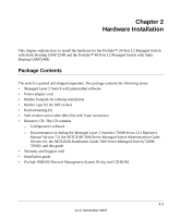
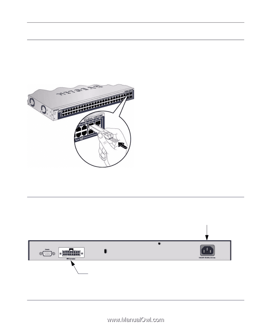
Managed Layer 2 Switches GSM7224R and GSM7248R Hardware Installation Guide SFP Modules The module bay accommodates a standard SFP module with an LC connector that is compatible with the IEEE 802.3z 1000BASE-X standard. SFP modules are sold separately. To install an SFP module insert the SFP module into the module bay. Press firmly to ensure that the module seats into the connector. Figure 2-2 Connecting a Redundant Power Supply (RPS) Each switch has a redundant power supply (RPS) connector and a power receptacle on the rear. Power receptacle Figure 2-3 2-6 Redundant power supply connector v1.0, November 2007 Hardware Installation
-
 1
1 -
2
-
3
-
4
-
5
-
6
-
7
-
8
-
9
-
10
-
11
-
12
-
13
-
14
-
15
-
16
-
 17
17 -
 18
18 -
 19
19 -
 20
20 -
 21
21 -
 22
22 -
 23
23 -
 24
24 -
 25
25 -
 26
26 -
 27
27 -
28
-
29
-
30
-
31
-
32
-
33
-
34
 |
 |
Managed Layer 2 Switches GSM7224R and GSM7248R Hardware Installation Guide
2-6
Hardware Installation
v1.0, November 2007
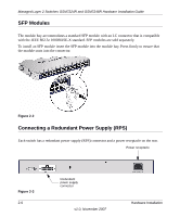
SFP Modules
The module bay accommodates a standard SFP module with an LC connector that is compatible
with the IEEE 802.3z 1000BASE-X standard.
SFP modules are sold separately.
To install an SFP module insert the SFP module into the module bay. Press firmly to ensure that
the module seats into the connector.
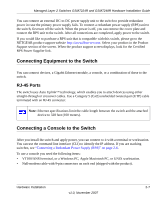
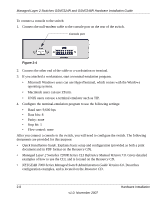
Connecting a Redundant Power Supply (RPS)
Each switch has a redundant power supply (RPS) connector and a power receptacle on the rear.
Figure 2-2
Figure 2-3
Power receptacle
Redundant
power supply
connector