Netgear GSM7248R GSM7224R / GSM7248R Hardware Installation Guide - Page 19
Installation, Selecting a Location
 |
View all Netgear GSM7248R manuals
Add to My Manuals
Save this manual to your list of manuals |
Page 19 highlights
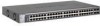
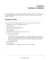
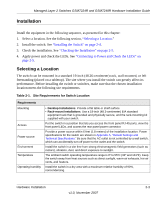
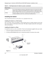
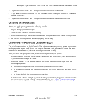
Managed Layer 2 Switches GSM7224R and GSM7248R Hardware Installation Guide Installation Install the equipment in the following sequence, as presented in this chapter: 1. Select a location. See the following section, "Selecting a Location." 2. Install the switch. See "Installing the Switch" on page 2-4. 3. Check the installation. See "Checking the Installation" on page 2-5. 4. Apply power and check the LEDs. See "Connecting to Power and Check the LEDs" on page 2-5. Selecting a Location The switch can be mounted in a standard 19-inch (48.26-centimeter) rack, wall mounted, or left freestanding (placed on a tabletop). The site where you install the switch can greatly affect its performance. Before installing the switch or switches, make sure that the chosen installation location meets the following site requirements. Table 2-1. Site Requirements for Switch Location Requirements Mounting Access Power source Environment Temperature Operating humidity • Desktop Installations. Provide a flat table or shelf surface. • Rack-mount Installations. Use a 19-inch (48.3-centimeter) EIA standard equipment rack that is grounded and physically secure, and the rack-mounting kit supplied with your switch. Put the switch in a position that lets you access the front panel RJ-45 ports, view the front panel LEDs, and access the rear panel power connector. Provide a power source within 6 feet (1.8 meters) of the installation location. Power specifications for the switch are shown in Appendix A, "Default Settings and Technical Specifications." Be sure that the AC outlet is not controlled by a wall switch, which can accidentally turn off power to the outlet and the switch. Install the switch in a site free from strong electromagnetic field generators (such as motors), vibration, dust, and direct exposure to sunlight. The ambient switch operating temperature range is 0º to 55ºC (32º and 131ºF). Keep the switch away from heat sources such as direct sunlight, warm-air exhausts, hot-air vents, and heaters. Install the switch in a dry area with a maximum relative humidity of 90%, noncondensing. Hardware Installation 2-3 v1.0, November 2007
-
 1
1 -
2
-
3
-
4
-
5
-
6
-
7
-
8
-
9
-
10
-
11
-
12
-
13
-
 14
14 -
 15
15 -
 16
16 -
 17
17 -
 18
18 -
 19
19 -
 20
20 -
 21
21 -
 22
22 -
 23
23 -
 24
24 -
25
-
26
-
27
-
28
-
29
-
30
-
31
-
32
-
33
-
34
 |
 |