Netgear GSM7248R GSM7224R / GSM7248R Hardware Installation Guide - Page 23
Connecting Equipment to the Switch, RJ-45 Ports
 |
View all Netgear GSM7248R manuals
Add to My Manuals
Save this manual to your list of manuals |
Page 23 highlights
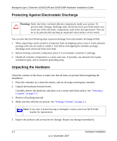
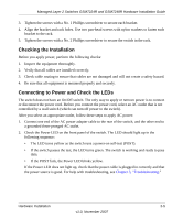
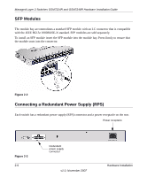
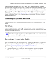
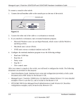
Managed Layer 2 Switches GSM7224R and GSM7248R Hardware Installation Guide You can connect an external DC-to-DC power supply unit to the switch to provide redundant power in case the primary power supply fails. To connect a redundant power supply (RPS) unit to the switch, first turn off the switch. When the power is off, you can remove the cover plate and connect the RPS unit to the switch. After all connections are completed, apply power to the switch. If you would like to purchase a RPS unit that is compatible with this switch, please go to the NETGEAR product support website http://www.kbserver.com. Select your product in the Product Support section of the screen. When the product support screen displays, look for the Certified RPS Power Supplier link. Connecting Equipment to the Switch You can connect devices, a Gigabit Ethernet module, a console, or a combination of these to the switch. RJ-45 Ports The switch uses Auto Uplink™ technology, which enables you to attach devices using either straight-through or crossover cables. Use a Category 5 (Cat5) unshielded twisted-pair (UTP) cable terminated with an RJ-45 connector. Note: Ethernet specifications limit the cable length between the switch and the attached device to 328 feet (100 meters). Connecting a Console to the Switch After you install the switch and apply power, you can connect to it with a terminal or workstation. You can use the command line interface (CLI) to identify the IP address. If you are stacking switches, see "Connecting a Redundant Power Supply (RPS)" on page 2-6. To use a console you need the following items: • VT100/ANSI terminal, or a Windows PC, Apple Macintosh PC, or UNIX workstation. • Null-modem cable with 9-pin connectors on each end (shipped with the product). Hardware Installation 2-7 v1.0, November 2007
-
 1
1 -
2
-
3
-
4
-
5
-
6
-
7
-
8
-
9
-
10
-
11
-
12
-
13
-
14
-
15
-
16
-
17
-
 18
18 -
 19
19 -
 20
20 -
 21
21 -
 22
22 -
 23
23 -
 24
24 -
 25
25 -
 26
26 -
 27
27 -
 28
28 -
29
-
30
-
31
-
32
-
33
-
34
 |
 |
