Netgear R6230 User Manual - Page 11
Ports, Buttons, and Connectors on the Back Panel, Table 2. LED descriptions Continued
 |
View all Netgear R6230 manuals
Add to My Manuals
Save this manual to your list of manuals |
Page 11 highlights
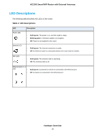
AC1200 Smart WiFi Router with External Antennas Table 2. LED descriptions (Continued) LED USB LED WPS LED Description • Solid green. A USB device is connected and is ready. • Blinking. A USB device is plugged in and is trying to connect. • Off. No USB device is connected, or someone clicked the Safely Remove Hardware button and it is now safe to remove the attached USB device. The WPS LED blinks green during the WPS process and then lights solid green. • Blinking for two minutes. The router's WPS button was pressed and the router is trying to connect to a WPS-enabled device. • Solid green. The router connected to a WPS-enabled device. Ports, Buttons, and Connectors on the Back Panel The back panel of the router provides ports, buttons, and a DC power connector. Figure 2. Router back panel In addition to the two antennas, the back panel contains the following components: • WPS button. Use this button to connect WPS-enabled devices to the router. • WiFi On/Off button. Pressing this button for two seconds turns the WiFi radios on and off. • USB port. Use the USB 2.0 port to connect the router to a USB device such as a printer. • Ethernet LAN ports. Use the four Gigabit Ethernet RJ-45 LAN ports to connect the router to LAN devices. Hardware Overview 11
-
 1
1 -
2
-
3
-
4
-
5
-
 6
6 -
 7
7 -
 8
8 -
 9
9 -
 10
10 -
 11
11 -
 12
12 -
 13
13 -
 14
14 -
 15
15 -
 16
16 -
17
-
18
-
19
-
20
-
21
-
22
-
23
-
24
-
25
-
26
-
27
-
28
-
29
-
30
-
31
-
32
-
33
-
34
-
35
-
36
-
37
-
38
-
39
-
40
-
41
-
42
-
43
-
44
-
45
-
46
-
47
-
48
-
49
-
50
-
51
-
52
-
53
-
54
-
55
-
56
-
57
-
58
-
59
-
60
-
61
-
62
-
63
-
64
-
65
-
66
-
67
-
68
-
69
-
70
-
71
-
72
-
73
-
74
-
75
-
76
-
77
-
78
-
79
-
80
-
81
-
82
-
83
-
84
-
85
-
86
-
87
-
88
-
89
-
90
-
91
-
92
-
93
-
94
-
95
-
96
-
97
-
98
-
99
-
100
-
101
-
102
-
103
-
104
-
105
-
106
-
107
-
108
-
109
-
110
-
111
-
112
-
113
-
114
-
115
-
116
-
117
-
118
-
119
-
120
-
121
-
122
-
123
-
124
-
125
-
126
-
127
-
128
-
129
-
130
-
131
-
132
-
133
-
134
-
135
-
136
-
137
 |
 |
