Netgear XM128 XM128 Installation Guide - Page 13
Physical Description, Front Panel
 |
View all Netgear XM128 manuals
Add to My Manuals
Save this manual to your list of manuals |
Page 13 highlights
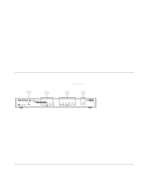
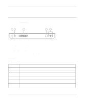
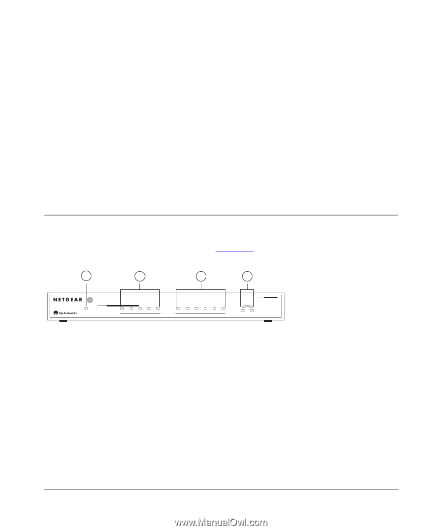
Chapter 2 Physical Description This chapter provides information about the hardware features of the Model XM128U ISDN Digital Modem. Use the key at the bottom of each illustration to identify the panel components. Front Panel For easier management and control of the Model XM128U modem, familiarize yourself with the components on the front panel, as illustrated in Figure 2-1. 1 2 3 4 U INTERFACE 128Kpbs ISDN Digital Modem PWR D B1 B2 AA CP ISDN DTR DSR RTS CTS TD RD COM MODELXM128 1 2 8262EA Key: 1 = PWR (power) LED 2 = ISDN LEDs 3 = RS-232 COM LEDs 4 = PHONE 1 and PHONE 2 LEDs Figure 2-1. Front panel of the Model XM128U modem (with S/T interface) Physical Description 2-1
-
 1
1 -
2
-
3
-
4
-
5
-
6
-
7
-
 8
8 -
 9
9 -
 10
10 -
 11
11 -
 12
12 -
 13
13 -
 14
14 -
 15
15 -
 16
16 -
 17
17 -
 18
18 -
19
-
20
-
21
-
22
-
23
-
24
-
25
-
26
-
27
-
28
-
29
-
30
-
31
-
32
-
33
-
34
-
35
-
36
-
37
-
38
-
39
-
40
-
41
-
42
 |
 |
Physical Description
2-1
Chapter 2
Physical Description
This chapter provides information about the hardware features of the Model XM128U ISDN
Digital Modem. Use the key at the bottom of each illustration to identify the panel components.
Front Panel
For easier management and control of the Model XM128U modem, familiarize yourself with the
components on the front panel, as illustrated in
Figure 2-1
.
Key:
1 = PWR (power) LED
2 = ISDN LEDs
3 = RS-232 COM LEDs
4 = PHONE 1 and PHONE 2 LEDs
Figure 2-1.
Front panel of the Model XM128U modem (with S/T interface)
8262EA
DTR
DSR
RTS
CTS
TD
D
PWR
B1
B2
AA
CP
ISDN
RD
1
2
ISDN
Digital Modem
INTERFACE
128Kpbs
MODEL
XM128
U
COM
2
3
4
1