Netgear XM128 XM128 Installation Guide - Page 14
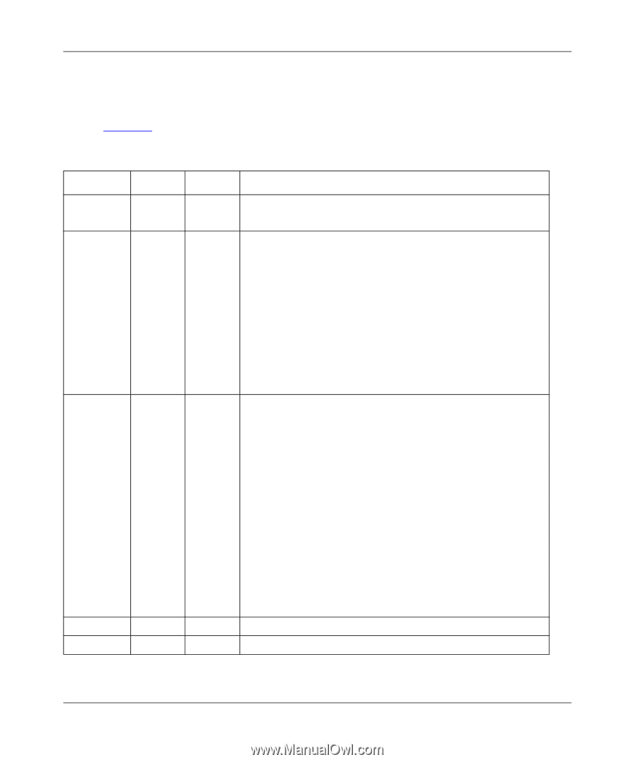
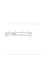
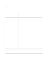
LEDs, LEDs on the front panel of the Model XM128U modem allow you to monitor and diagnose the, device.
 |
View all Netgear XM128 manuals
Add to My Manuals
Save this manual to your list of manuals |
Page 14 highlights
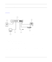
Getting Started Using FirstGear for the Model XM128U ISDN Digital Modem LEDs LEDs on the front panel of the Model XM128U modem allow you to monitor and diagnose the device. Table 2-1 describes each LED. Table 2-1. LED descriptions Label Color Activity Description PWR (Power) Green ISDN LEDs: D Green B1 Green B2 Green AA Green CP Green RS-232 COM LEDs: DTR Green DSR Green RTS Green CTS Green TD Green RD Green PHONE 1 PHONE 2 Green Green On Power is supplied to the modem. On Blinking On On On Blinking On The ISDN link on the D channel is active. The Model XM128U modem is attempting to make a connection to the switch. A connection is established to the B1 channel. A connection is established to the B2 channel. The Model XM128U modem is in the automatic answering mode. An incoming call is ringing. Compression is active on either of the B channels. On The data terminal or computer connected to the DTE port on the Model XM128U modem is ready to communicate. On The Model XM128U modem is ready to communicate with the connected data terminal or computer. On The data terminal or computer connected to the DTE port on the Model XM128U modem is ready to transmit data. On The Model XM128U modem is ready to accept data from the connected data terminal or computer. On The data terminal or computer connected to the Model XM128U modem is transmitting data to the modem. On The data terminal or computer connected to the Model XM128U modem is receiving data from the DTE port of the modem. On The telephone connected to the port is in use. On The telephone connected to the port is in use. 2-2 Physical Description
-
 1
1 -
2
-
3
-
4
-
5
-
6
-
7
-
8
-
 9
9 -
 10
10 -
 11
11 -
 12
12 -
 13
13 -
 14
14 -
 15
15 -
 16
16 -
 17
17 -
 18
18 -
 19
19 -
20
-
21
-
22
-
23
-
24
-
25
-
26
-
27
-
28
-
29
-
30
-
31
-
32
-
33
-
34
-
35
-
36
-
37
-
38
-
39
-
40
-
41
-
42
 |
 |