NordicTrack Cxt 1200 Elliptical Uk Manual - Page 7
the Left Upper Body Leg out of the Upper Body Arm
 |
View all NordicTrack Cxt 1200 Elliptical manuals
Add to My Manuals
Save this manual to your list of manuals |
Page 7 highlights
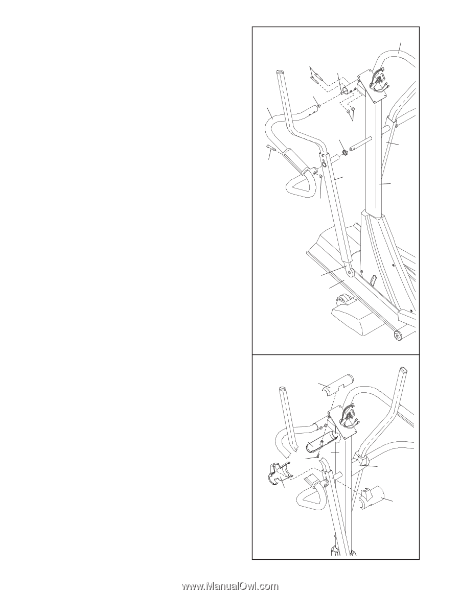
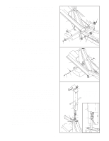
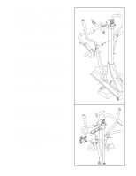
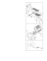
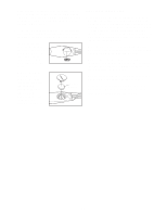
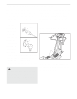
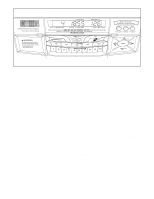
5. Slide a Weld Spacer (119) onto the axle on the left side of the Upright (2), with the open side of the Weld Spacer facing the Upright. Locate the Upper Body Arm (118) that has the Left Upper Body Leg (31) inside of it (the Left Upper Body Leg is marked with a sticker). Hold the Upper Body Arm with one hand, hold the Left Upper Body Leg with your other hand, and slide the Upper Body Arm onto the axle on the left side of the Upright (2). Then, slide the Left Upper Body Leg out of the Upper Body Arm until it rests on the Ramp (3). Have another person hold the Left Handlebar (24) near the Upright (2) as shown. Connect the left Pulse Sensor Wire (20) to the Pulse Extension Wire (114). Slide the upper end of the Left Handlebar (24) into the tube on the front of the Upright (2), whilst sliding the lower end of the Left Handlebar onto the axle on the left side of the Upright. Attach the upper end of the Left Handlebar with two M8 x 41mm Button Bolts (85) and two M8 Jam Nuts (86); be careful not to damage the Wires (20, 114) as you insert the Button Bolts. Make sure that the Jam Nuts are resting in the hexagonal holes in the Left Handlebar. Attach the lower end of the Left Handlebar with an M8 x 38mm Button Bolt (105) and an M8 Jam Nut (86). Attach the other Upper Body Arm (118) and the Right Handlebar (23) to the Upright (2) in the same way. 5 24 105 85 114 20 86 119 118 86 31 3 23 118 2 6. Look inside one of the Handlebar Covers (26) and locate the square tabs connecting the two halves. 6 Gently lift the tabs and disconnect the halves. Hold the two halves of the Handlebar Cover (26) around the tube on the left side of the Upright (2). Align the halves and press them together until they lock. Attach the other Handlebar Cover (26) to the right side of the Upright (2) in the same way. Hold the halves of the Upper Handlebar Cover (25) around the tube on the front of the Upright (2); be careful not to damage the Wires (not shown). Attach the Upper Handlebar Cover with an M4 x 12mm Round Head Screw (96). 25 25 2 96 26 26 26 7
-
 1
1 -
 2
2 -
 3
3 -
 4
4 -
 5
5 -
 6
6 -
 7
7 -
 8
8 -
 9
9 -
 10
10 -
 11
11 -
 12
12 -
13
-
14
-
15
-
16
-
17
-
18
-
19
-
20
-
21
-
22
-
23
-
24
-
25
-
26
-
27
-
28
-
29
-
30
-
31
-
32
 |
 |