NordicTrack Cxt 1200 Elliptical Uk Manual - Page 8
and the Left Upper Body Leg 31 to the Wheel Frame
 |
View all NordicTrack Cxt 1200 Elliptical manuals
Add to My Manuals
Save this manual to your list of manuals |
Page 8 highlights
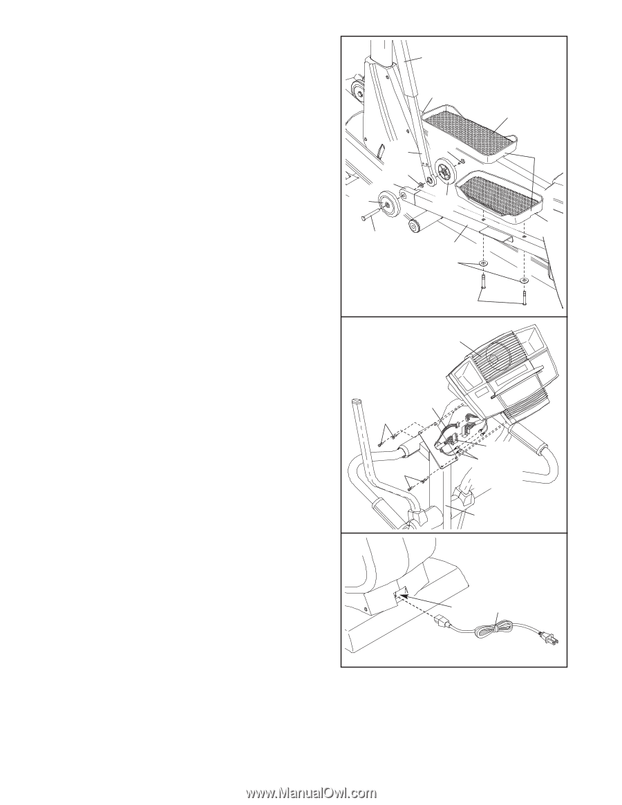
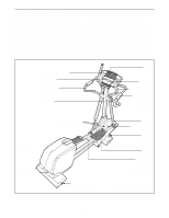
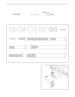
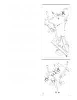
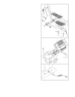
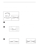
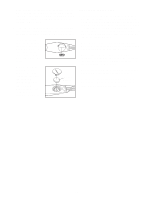
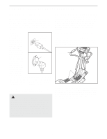
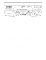
7. Identify the Left Pedal (10), which is widest at the rear and has an opening on the left side. Attach the Left Pedal to the Left Pedal Leg (4) with two M8 x 60mm Button Screws (83) and two M8 Split Washers. Attach the Right Pedal (11) to the Right Pedal Leg (5) in the same way. Attach two Pedal Wheels (28), an M10 Washer (126), and the Left Upper Body Leg (31) to the Wheel Frame (30) on the Left Pedal Leg (4) with an M10 x 78mm Bolt Set (65). Make sure that the Bolt Set, Pedal Wheels, Washer, and Upper Body Leg are oriented as shown. Attach the other two Pedal Wheels, the Right Upper Body Leg, and an M10 Washer (not shown) to the Wheel Frame (not shown) on the Right Pedal Leg (5) in the same way. 7 118 5 31 65 126 30 28 28 65 4 M8 Split Washers 11 Wide End 10 8. Have another person hold the Console (17) near the Upright (2). Connect the Upper Wire Harness (115) to the wire harness on the Console (17). Connect the Pulse Extension Wire (114) to the pulse wire on the Console. Next, locate the two ground wires that are attached with a screw to the Upright (2). Connect the ground wires to the two smallest wires on the Console. Carefully insert all excess wiring up into the Console (17) and down into the Upright (2). Attach the Console to the Upright with four M4 x 16mm Screws (98). (Note: The Screws may be shipped in the console box.) Be careful to avoid pinching the wires. 9. Plug the Power Cord (116) into the Power Socket (117) at the rear of the elliptical exerciser. 83 8 Do not pinch 17 the wires during this step. 114 98 98 115 Ground Wires 2 9 117 116 10.Make sure that all parts of the elliptical exerciser are properly tightened. Cover the floor beneath the elliptical exerciser to protect the floor from damage. Note: Some extra hardware may be left over. 8
-
 1
1 -
2
-
 3
3 -
 4
4 -
 5
5 -
 6
6 -
 7
7 -
 8
8 -
 9
9 -
 10
10 -
 11
11 -
 12
12 -
 13
13 -
14
-
15
-
16
-
17
-
18
-
19
-
20
-
21
-
22
-
23
-
24
-
25
-
26
-
27
-
28
-
29
-
30
-
31
-
32
 |
 |