Panasonic BTLH80W BTLH80W User Guide - Page 22
Vf Config
 |
View all Panasonic BTLH80W manuals
Add to My Manuals
Save this manual to your list of manuals |
Page 22 highlights
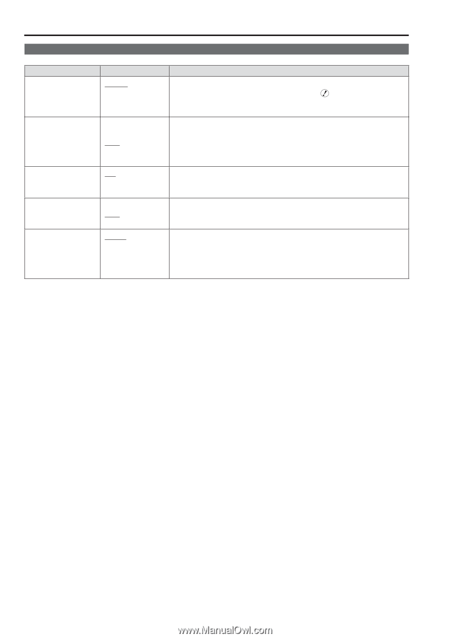
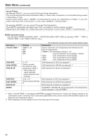
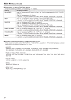
Main Menu (continued) VF CONFIG Sub menu VF CONTROL Settings VF-CH ALL-CH CROSS HATCH HIGH LOW OFF REAR TALLY ZEBRA RETURN CH∗1∗2 ON OFF ON OFF YPBPR VF VIDEO SDI The underlined values are factory preset setting values. Explanation Used to select the input line for the VF function of the monitor. (VF function: tally lamp lit, zebra displayed, displayed) Only enabled when the VF line is selected. Enabled with all input lines. Used to set whether to display a cross hatch and select its density level. 70/256 (displays with a dense cross hatch) 20/256 (displays with a light cross hatch) Not displayed. Used to allow control of the tally lamp on the rear of the monitor. Lamp lights when TALLY control from a GPI/camera is ON. Lamp does not light. Used to set ZEBRA information in the camera. Sets the information to ON. Sets the information to OFF. Used to select the signal input line by operating the RETURN (RET) button of the camera lens. When there is no SDI input unit (option), the SDI item is displayed in gray and cannot be set. • The priority sequence for GPI control and RS-232C is as follows: GPI > VF CONFIG > RS-232C. ∗1 RETURN CH operates when VF CONTROL is set to ALL-CH. It is not affected by the various line ON/OFF settings in the INPUT SELECT menu (→ page 29). (Input lines that are set with RETURN CH are enabled even if they are set to OFF in INPUT SELECT.) ∗2 A function to be used with future Panasonic camera-recorders. 22
-
 1
1 -
2
-
3
-
4
-
5
-
6
-
7
-
8
-
9
-
10
-
11
-
12
-
13
-
14
-
15
-
16
-
 17
17 -
 18
18 -
 19
19 -
 20
20 -
 21
21 -
 22
22 -
 23
23 -
 24
24 -
 25
25 -
 26
26 -
 27
27 -
28
-
29
-
30
-
31
-
32
-
33
-
34
-
35
-
36
-
37
-
38
 |
 |