4
Read this first! (For BT-LH80WP) . . . . . . . . . . . . . . . 2
Read this first! (For BT-LH80WE) . . . . . . . . . . . . . . . 3
Standard accessory . . . . . . . . . . . . . . . . . . . . . . . . .4
Optional unit . . . . . . . . . . . . . . . . . . . . . . . . . . . . . . .4
Precautions for use . . . . . . . . . . . . . . . . . . . . . . . . . . 5
Outline . . . . . . . . . . . . . . . . . . . . . . . . . . . . . . . . . . . .6
Dimensions . . . . . . . . . . . . . . . . . . . . . . . . . . . . . . . .6
Controls and Their Functions . . . . . . . . . . . . . . . . .7
Front panel . . . . . . . . . . . . . . . . . . . . . . . . . . . . . . . . 7
Rear panel . . . . . . . . . . . . . . . . . . . . . . . . . . . . . . . . 8
Supplying the power . . . . . . . . . . . . . . . . . . . . . . . . . 9
Using the Anton/Bauer type battery pack. . . . . . . . . 9
Using a V-mount type battery pack . . . . . . . . . . . . . 9
Using an external DC power supply. . . . . . . . . . . . 10
VF Function . . . . . . . . . . . . . . . . . . . . . . . . . . . . . . . 11
How to Use the On Screen Menu . . . . . . . . . . . . . . 12
Operating status display . . . . . . . . . . . . . . . . . . . .12
Picture adjusting knob status . . . . . . . . . . . . . . . . . 12
Sharpness display . . . . . . . . . . . . . . . . . . . . . . . . . 13
Function display . . . . . . . . . . . . . . . . . . . . . . . . . . . 13
DC power supply voltage and battery level display 13
Menu display . . . . . . . . . . . . . . . . . . . . . . . . . . . . . 13
Menu operations . . . . . . . . . . . . . . . . . . . . . . . . . .14
User Data . . . . . . . . . . . . . . . . . . . . . . . . . . . . . . . . . 15
Saving user data . . . . . . . . . . . . . . . . . . . . . . . . . .15
Loading user data . . . . . . . . . . . . . . . . . . . . . . . . .15
Main Menu . . . . . . . . . . . . . . . . . . . . . . . . . . . . . . . .16
Menu configuration . . . . . . . . . . . . . . . . . . . . . . . .16
MARKER . . . . . . . . . . . . . . . . . . . . . . . . . . . . . . . . 17
Types of MARKER . . . . . . . . . . . . . . . . . . . . . . . . . 18
VIDEO CONFIG . . . . . . . . . . . . . . . . . . . . . . . . . . . 19
SYSTEM CONFIG . . . . . . . . . . . . . . . . . . . . . . . . . 21
VF CONFIG . . . . . . . . . . . . . . . . . . . . . . . . . . . . . . 22
FUNCTION . . . . . . . . . . . . . . . . . . . . . . . . . . . . . .23
GPI . . . . . . . . . . . . . . . . . . . . . . . . . . . . . . . . . . . . . 28
INPUT SELECT . . . . . . . . . . . . . . . . . . . . . . . . . . . 29
CONTROL . . . . . . . . . . . . . . . . . . . . . . . . . . . . . . . 30
HOURMETER . . . . . . . . . . . . . . . . . . . . . . . . . . . . 30
REMOTE Specifications . . . . . . . . . . . . . . . . . . . . . 31
GPI terminal . . . . . . . . . . . . . . . . . . . . . . . . . . . . . . 31
RS-232C terminal . . . . . . . . . . . . . . . . . . . . . . . . .32
RS-232C REMOTE operation method . . . . . . . . . . 32
Maintenance Inspections . . . . . . . . . . . . . . . . . . . . 35
Error/Warning Displays. . . . . . . . . . . . . . . . . . . . . . 36
Maintenance . . . . . . . . . . . . . . . . . . . . . . . . . . . . . . . 36
Specifications . . . . . . . . . . . . . . . . . . . . . . . . . . . . .36
Contents
Standard accessory
• Battery mount terminal block [2 screws (M3 x 4) included] × 1
• Screw spacer (already installed on the unit) × 1
Optional unit
• SDI input unit
BT-YA80G
• VF Cable Set
BT-CS80G
(DC cable also included
→
page 11)

 1
1 2
2 3
3 4
4 5
5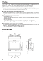 6
6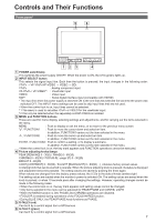 7
7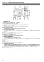 8
8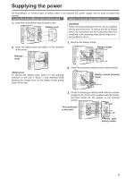 9
9 10
10