Panasonic TH-50PX600 Operating Instructions - Page 24
Recommended AV Connections
 |
View all Panasonic TH-50PX600 manuals
Add to My Manuals
Save this manual to your list of manuals |
Page 24 highlights
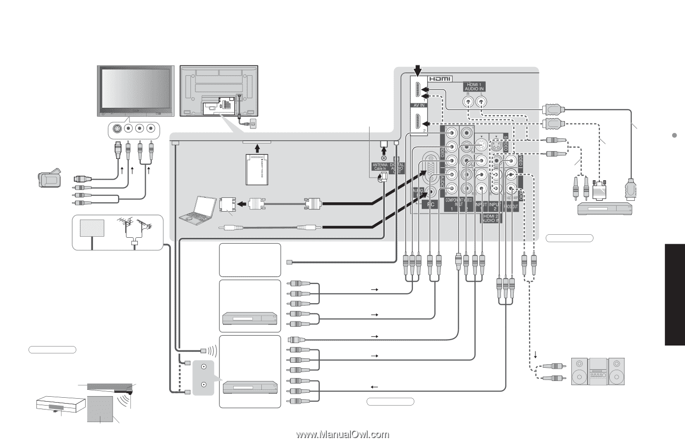
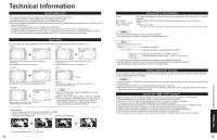
Recommended AV Connections These diagrams show our recommendations for how to connect the TV unit to your various equipment. For other connections, consult the instructions of each equipment, and the specifications (p. 61). For additional assistance, please visit our website at : www.panasonic.com www.panasonic.ca ■To watch camcorder images INPUT3 Back of the unit G-LINK IR Blaster (Supplied) ■To watch cable TV AC Cord (Connect after all the other connections.) Camcorder S-Video Camcorder VCR/S-Video VCR DVD Player Cable TV or ■ PC Computer CableCARD™ RGB PC cable Conversion adapter (if necessary) Audio cable •For receiving digital broadcasting of cable TV, connect Cable TV directly to "ANTENNA Cable In" terminal. • CableCARD™ Insert a card to watch cable channels serving digital high-definition video. Consult the cable company for information. •IR Blaster (p. 56) You can operate the VCR from the TV remote control or reserve recording with TV Guide. Install the light emitting area of the IR Blaster near the signal-receiving area for the remote control on the VCR. Note •To make schedule recording using TV Guide with IR blaster, you have to select in your VCR Line-1 (L-1) and set your VCR in OFF condition. (Refer to the Operating Instruction manual of VCR) Top shelf of TV stand VCR Mount with two-sided tape • Digital audio amplifier • Theater system ■To watch DVDs DVD Player Set Top Box (VCR Only) or RF OUT ■To record TV shows DVD Recorder / VCR RF IN 46 Signal-emitting area of remote control VCR Signal-emitting area Signal-receiving area of remote control ■Recommended HDMI Connections (p. 36-37) F-Type Antenna or Adapter ■To watch digital video image or or HDMI cable HDMI-DVI conversion cable Audio cable S-Video signals have priority DVD Player or Set Top Box (HDMI compatible machines only) Note •The picture and audio input signals connected to a terminal specified in "Progout stop" (p. 32) cannot be output from "OUTPUT" terminals. However, audio output can be obtained from the optical •Digital Audio Out terminal. To prevent howling and image oscillation, set the "Prog-out-stop" setting when connecting •VCR with loop-connection. (p. 32) When a device (STB, DVD, etc.) is connected to the HDMI or COMPONENT terminals, only audio signals will be output. No video signals will be output. ■To listen to the TV through speakers Amplifier •Turn Off the TV speakers. (p. 32 "Speakers") Caution ••For Antenna connection via VCR, please refer to the Operating Instructions for your VCR. If you use both IR Blaster and "HDAVI Control" (P. 34) for the same Panasonic DIGA (with VCR type), please set "Power off link" (under "Other adjust" of "Setup" menu ) to "No" (P. 34), to avoid failure for your recording. 47 Advanced Recommended AV Connections
-
 1
1 -
2
-
3
-
4
-
5
-
6
-
7
-
8
-
9
-
10
-
11
-
12
-
13
-
14
-
15
-
16
-
17
-
18
-
 19
19 -
 20
20 -
 21
21 -
 22
22 -
 23
23 -
 24
24 -
 25
25 -
 26
26 -
 27
27 -
 28
28 -
 29
29 -
30
-
31
-
32
-
33
-
34
-
35
-
36
-
37
-
38
-
39
-
40
-
41
-
42
-
43
-
44
-
45
-
46
-
47
-
48
-
49
-
50
-
51
-
52
-
53
-
54
-
55
-
56
-
57
-
58
-
59
-
60
-
61
-
62
-
63
-
64
-
65
 |
 |