Panasonic WJRT416V WJRT416V User Guide - Page 42
Connection, Basic connection - digital camera
 |
View all Panasonic WJRT416V manuals
Add to My Manuals
Save this manual to your list of manuals |
Page 42 highlights
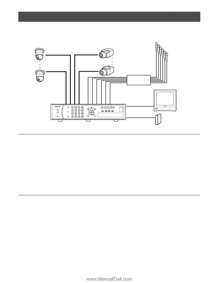
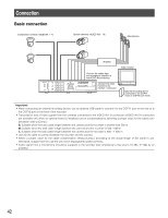
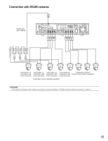
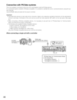
Connection Basic connection Combination cameras (VIDEO IN 1 - 4) System cameras (VIDEO IN 5 - 16) Microphones ERROR ALARM TIMER OPERATE HDD SEQUENCE 1 1 2 3 4 2 MULTI 5 6 7 8 3 SCREEN 4 9 10/0 11 12 5 ALARM RESET 6 13 14 15 16 SETUP SEARCH COPY ESC SET Amplifier Video monitor Connect the cables from the microphone amplifier to the AUDIO IN connectors. STOP PLAY PAUSE REC REC STOP REV FWD SKIP - + Digital Disk Recorder WJ-RT416 Connect the video monitor to the monitor 1 connector. External recording device connected to the COPY1 (rear) or COPY2 port (front) Important: • When connecting an external recording device, use an optional USB cable to connect it to the COPY1 port on the rear or to the COPY2 port on the front of the recorder. • Transmission loss of video signals from the cameras connected to the VIDEO IN 1-8 connectors (VIDEO IN 5-8 connectors are available only when an optional board is installed) can be compensated by selecting a proper value for the cable compensation setting (Comp.). S: Suitable when the total cable length between the camera and the recorder is shorter than 500 m M: Suitable when the total cable length between the camera and the recorder is 500 - 900 m L: Suitable when the total cable length between the camera and the recorder is 900 - 1 200 m • Use 5C-2V cable to connect between the recorder and the camera. • Select a proper value for the cable compensation setting (Comp.) according to the actual length of the cable in use. Otherwise, images from the camera will not be displayed/recorded correctly. • Audio signal from a microphone should be supplied to the recorder after amplifying to line level (-10 dBv, 51 kΩ) by an amplifier. 42
-
 1
1 -
2
-
3
-
4
-
5
-
6
-
7
-
8
-
9
-
10
-
11
-
12
-
13
-
14
-
15
-
16
-
17
-
18
-
19
-
20
-
21
-
22
-
23
-
24
-
25
-
26
-
27
-
28
-
29
-
30
-
31
-
32
-
33
-
34
-
35
-
36
-
 37
37 -
 38
38 -
 39
39 -
 40
40 -
 41
41 -
 42
42 -
 43
43 -
 44
44 -
 45
45 -
 46
46 -
 47
47 -
48
-
49
-
50
-
51
-
52
-
53
-
54
-
55
-
56
-
57
-
58
-
59
-
60
-
61
-
62
-
63
-
64
-
65
-
66
-
67
-
68
-
69
-
70
-
71
-
72
-
73
-
74
-
75
-
76
-
77
-
78
-
79
-
80
 |
 |