Panasonic WJRT416V WJRT416V User Guide - Page 47
DIP Switch Setting, Add the recorder to a broadband WAN Wide Area Network
 |
View all Panasonic WJRT416V manuals
Add to My Manuals
Save this manual to your list of manuals |
Page 47 highlights
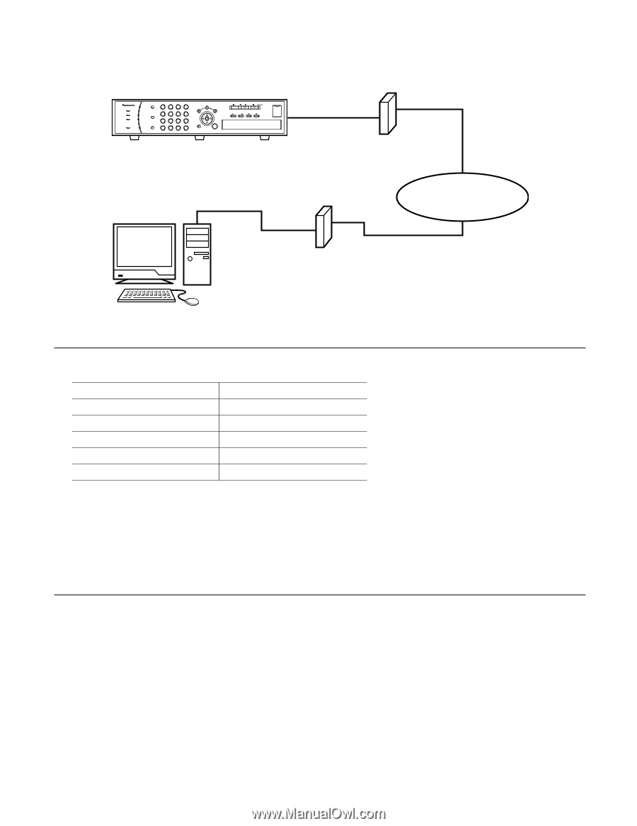
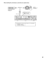
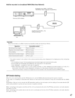
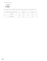
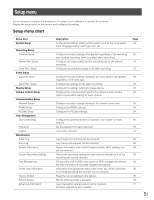
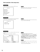
Add the recorder to a broadband WAN (Wide Area Network) Broadband router A (WAN → WJ-RT416) TCP/UDP port: 2000 (configured on the WJ-RT416) ERROR ALARM TIMER OPERATE HDD SEQUENCE 1 1 2 3 4 2 MULTI 5 6 7 8 3 SCREEN 4 9 10/0 11 12 5 ALARM RESET 6 13 14 15 16 SETUP SEARCH COPY ESC SET STOP PLAY PAUSE REC REC STOP REV FWD SKIP - + Digital Disk Recorder WJ-RT416 Server port: 2000 (editable) WAN Broadband router B (WAN → PC) UDP port: 999 (fixed) PC Important: When the recorder is in a WAN, maximum accessible number will become as follows. Operation Monitoring of live images Playback of recorded images Frame display Download of recorded images Audio transmission/reception Accessible number* Total of 16 areas Total of 4 areas 4 PCs (4 users) 4 PCs (4 users) 1 PC (1 user) * "Accessible number" is the number of the camera channels that can be displayed in the display area of the monitoring software. • It is necessary to log in first to play/download recorded images and transmit/receive audio. • If live images are transmitted using Multicast, the chart above is not applicable. • Only "Manager1" is capable of voice call. ( page 67) • When displaying images from 5 or more camera channels, or when displaying recorded images in an area on a multi-screen, only I-frame* will be displayed in all areas on a multi-screen and audio may not be heard. *: Short for intra frame. I-frame is an image that is to be inserted in the intra refresh period of MPEG images. DIP Switch Setting When the unit is used together with the PS·Data devices, use the RS485 cable provided with the system controller. In this case, it is necessary to terminate both devices on both ends of the connection if they are connected with the RS485 cable. Termination of this unit can be set with the DIP termination switch on the rear panel, and the setting of the mode selection DIP switch varies whether to use this unit as a receiver or a system controller. When connecting to the system controller and this unit is connected as the end of the PS·Data connection, set mode selection DIP switch 2 to "ON". When connecting to the system device and this unit is connected as the end of the PS·Data connection, set mode selection DIP switch 1 to "ON". 47
-
 1
1 -
2
-
3
-
4
-
5
-
6
-
7
-
8
-
9
-
10
-
11
-
12
-
13
-
14
-
15
-
16
-
17
-
18
-
19
-
20
-
21
-
22
-
23
-
24
-
25
-
26
-
27
-
28
-
29
-
30
-
31
-
32
-
33
-
34
-
35
-
36
-
37
-
38
-
39
-
40
-
41
-
 42
42 -
 43
43 -
 44
44 -
 45
45 -
 46
46 -
 47
47 -
 48
48 -
 49
49 -
 50
50 -
 51
51 -
 52
52 -
53
-
54
-
55
-
56
-
57
-
58
-
59
-
60
-
61
-
62
-
63
-
64
-
65
-
66
-
67
-
68
-
69
-
70
-
71
-
72
-
73
-
74
-
75
-
76
-
77
-
78
-
79
-
80
 |
 |